Installation
9229 0025 176 0E 51
2021-11-15
Connecting the low voltage for the withdrawable part
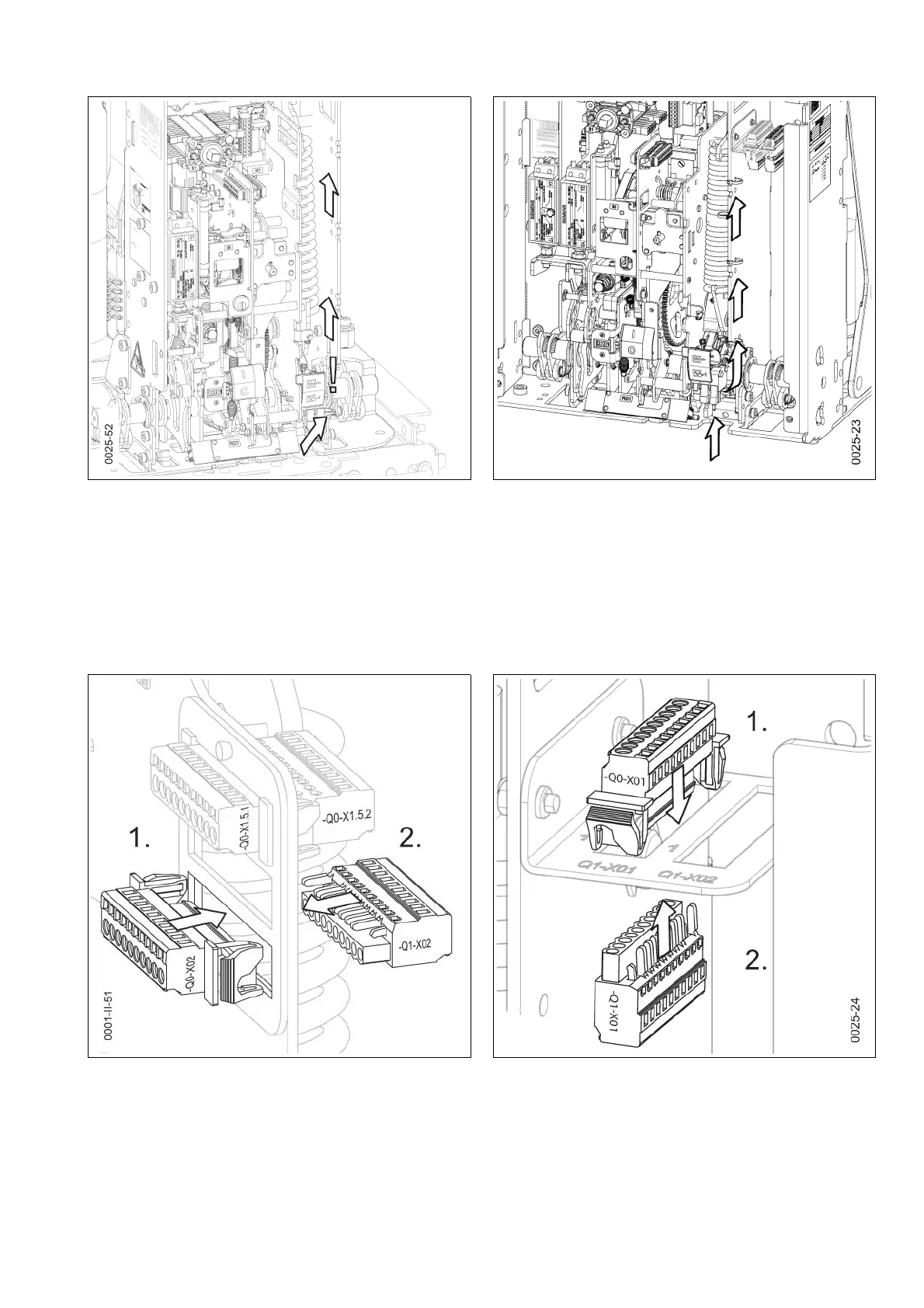
Laying the cable harness
(see Fig. 73)
• Feed the cable harness of the withdrawable part with the plugs (-Q0) along the
side wall through the vacuum circuit-breaker.
• Fix the cable harness to the existing cable harness using cable straps and
ensure there is sufficient distance from the spring state indicator.
Laying the cable harness
(see Fig. 74)
• Feed the cable harness of the withdrawable part with the plugs (-Q0) through
the vacuum circuit-breaker.
• Fix the cable harness to the right side wall with cable straps.
Mounting the plug • Insert the plug bottom (-Q0) into the frame as far as it will go and let it engage.
• Wire the plug (-Q1) and insert it (see “Wiring of connectors Q0-X1.1, Q0-X1.2,
Q0-X1.3” page 50).
Fig. 73 Laying the cable harness Fig. 74 Laying the cable harness
Fig. 75 Mounting the plug for the withdrawable part Fig. 76 Mounting the plug for the withdrawable part

 Loading...


