SIPART DR19
C73000-B7474-C140-06
67
Quick Reference Configuring
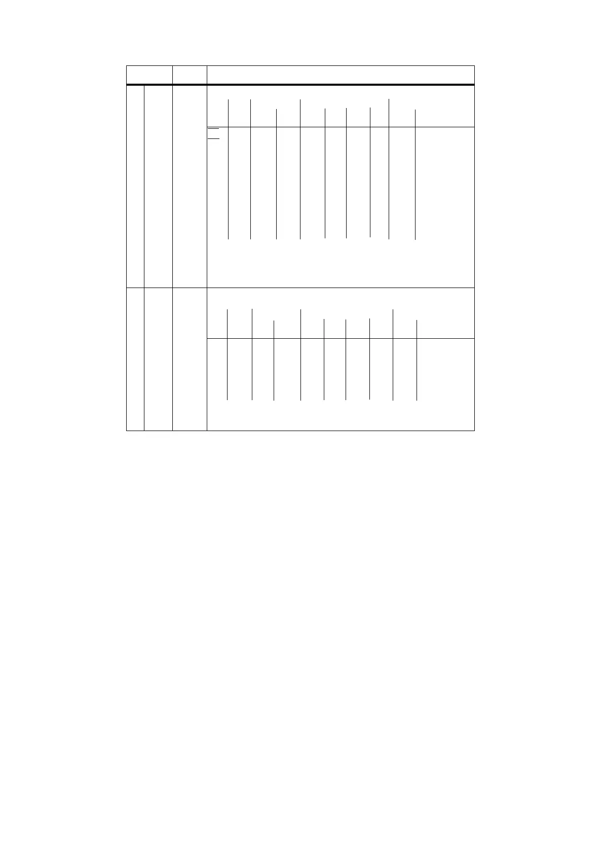
Allocation of signals to binary outputs
Basic unit Slot 3 Basic unit
none DO1 DO2 DO3 DO4 DO5 DO6 DO7 DO8
(relay) (relay)
S59
S60
S61
S62
S63
S64
S65
S66
S67
S68
S69
RB
[0] 1 2345678
RC
[0] 1 2345678
H[0]1 2345678
Nw[0] 1 2345678
A10[1]2345678
A20 1[2]345678
A3[0]1 2345678
A4[0]1 2345678
MUF[0]1 2345678
+∆w[0]1 2345678
-∆w[0]1 2345678
Notes:
• If DO1/2 or DO7/8 have been allocated ±∆y by S57, duplicated alloca-
tion is not possible.
• Allocation of various control signals to a digital output effects an OR
function!
Time bus/status signals: Allocation of digital signals of the program
controller to digital outputs
Basic unit Slot 3 Basic unit
none DO1 DO2 DO3 DO4 DO5 DO6 DO7 DO8
(relay) (relay)
S70
S71
S72
S73
S74
S75
Clb1[0]1 2345678
Clb2[0]1 2345678
Clb3[0]1 2345678
Clb4[0]1 2345678
Clb5[0]1 2345678
Clb6[0]1 2345678
Notes:
If DO1/2 or DO7/8 have been allocated ±∆y by S58, duplicated allocation
is not possible.
Config.
switch
Setting Function
DIGITAL INPUT PR
DIGITAL OUTPUTS
 Loading...


