SIPART DR19
C73000-B7474-C140-06
75
Quick Reference Configuring
Parameters when S5=6/7 (resistance based sensor)
1)
The decimal point in the measuring range must be observed!
Definition of parameters when SS5=6/7 (resistance based sensor)
CA1/
CE1
Trimming of measuring range
The measuring range, and consequently the measured value itself, can be corrected to
compensate for sensor tolerances to calibrate the instrument for use with other indica-
tors.
CA1 - for trimming at the lower end of the measuring range
CE1 - for trimming at the upper end of the measuring range
PC1 The PC1 resets the trimming performed using CA1/CE1.
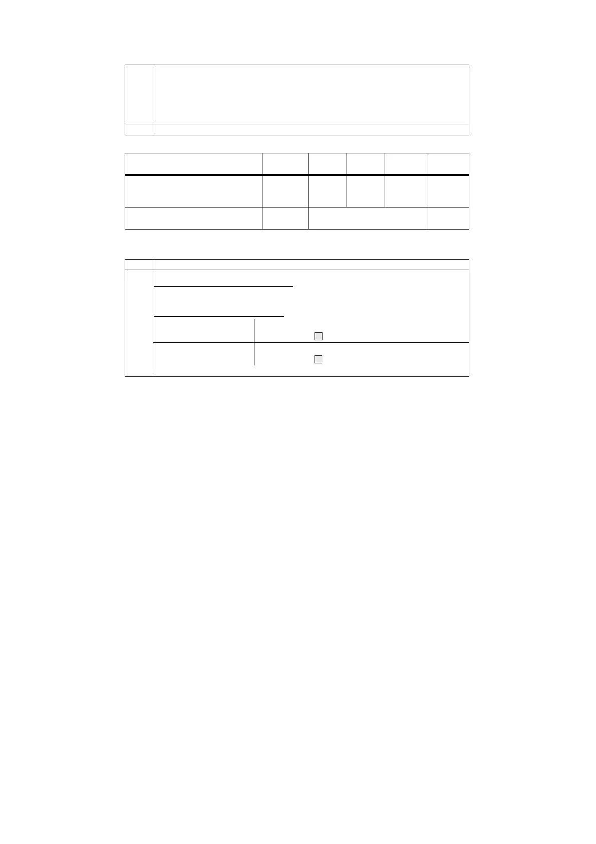
Parameter/Function Param.-
names
Min Max Factory
setting
Eng.
unit
Decimal point
Start of scale value
Full scale value
MP1
MA1
ME1
_.---
-1999
-1999
----
9999
9999
.-
0,0
100.0
-
Ω
Ω
Calibrated value for MA1
Calibrated value for ME1
CA1
1)
CE1
1)
present output value
present output value
%
%
MP1 MP1 defines the position of the decimal point for the measuring range.
MA1/
ME1
CA1/
CE1
Definition of measuring range
Method 1: resistance values are known
Select MA1 and ME1 parameters and enter known resistance values:
CA1 and CE1 parameters are ignored.
Method 2: resistance value unknown
Calibrate start of scale
value
• Set control element to 0% and select CA1 parameter;
• Press button (9) until 0.0 is displayed;
Calibrate full scale value
• Set control element to 100% and select CE1 parameter;
• Press button (9) until 100.0 is displayed;
Line resistance is then trimmed automatically; parameters MA1/ME1 are ignored.
---
 Loading...


