Assembly and Installation Information
SIPART DR22/DR24
C79000-M7474-C38-01
17
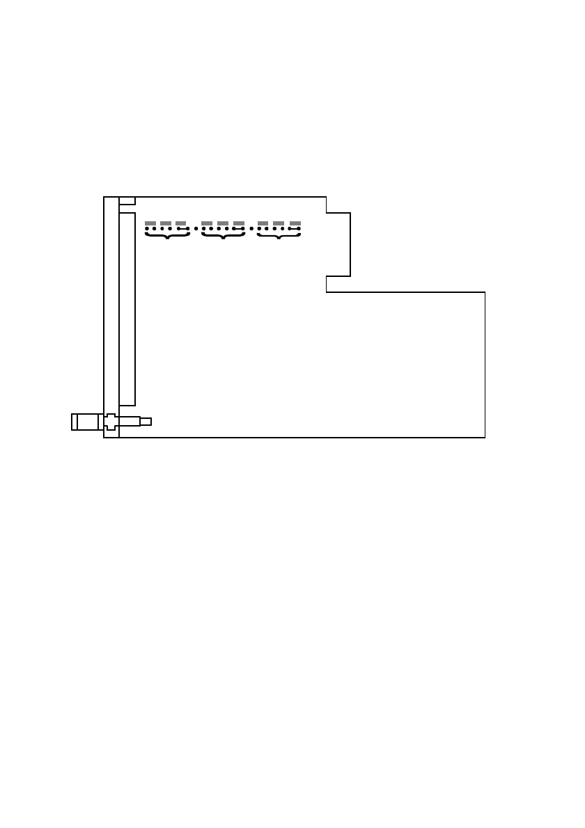
5.2 Switching AE1 to AE3
The inputs AE1 to AE3 can be switched on the main circuit board.
The following ranges are possible: 1V, 10V, I (20 mA).
Factory setting: I (20 mA)
AE3 AE2
AE1
1V 10V
Factory setting I (0 to 20 mA)
Main circuit board
C73451-A3001-L32
1V 10V
II
1V 10V
I
Figure 4 Switching on the main circuit board
Procedure:
1 Remove front module.
1.1 Remove the cover of the measuring position shield
1.2 Loosen the retaining screw
1.3 Remove the front module and loosen the plug-in connector to the main
circuit board
2 Unlock the main circuit board from the rear side (with a suitable screwdriver)
and pull out backwards from the housing.
3 Change the s ettings on the main circuit board (see Figure 3)
4 Insert main circuit board and lock.
5 Insert the front module and secure (remember the plug-in connector).
5.3 Labelling the Front Mask
The front mask can be removed and labelled with the specific application. To do
this, pull the mask down (tweezers or small pliers), label, and replace.
 Loading...


