NOTICE
Freezing of the exhaust air outlets
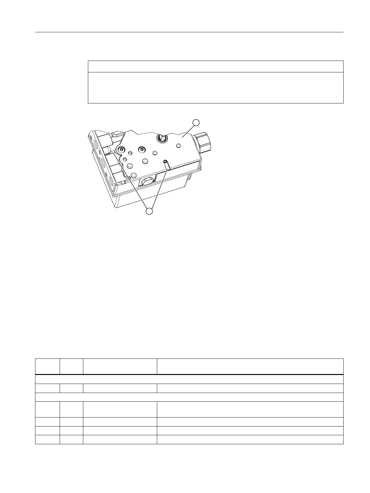
The exhaust air outlets ② can ice up. The function of the device is impaired.
• Do not install the positioner with the base plate ① pointing up.
① Base plate
② Exhaust air outlets
Figure 4-1 Exhaust air outlets, base plate
4.2 Mounting to linear actuator
Requirements
Depending on the stroke height, you will need the following mounting kit:
• 3 to 35 mm mounting kit 6DR4004-8V
• 35 to 130 mm mounting kit 6DR4004-8V and additional 6DR4004-8L
Procedure
Sr. no.
*)
Quan‐
tity
Name Note
6DR4004-8L:
① 1 Lever For the range of stroke from 10 to 130 mm
6DR4004-8V:
① 1 NAMUR mounting bracket
IEC 60534
Standardized connection point for mount with n, column or plane surface
② 1 Pick-up bracket Guides the pulley with the carrier pin and rotates the lever arm.
③ 2 Clamping piece Installs the pick-up bracket on the actuator spindle
④ 1 Carrier pin Installation with pulley ⑤ on lever ⑥
Installing/mounting
4.2 Mounting to linear actuator
SIPART PS100
Compact Operating Instructions, 05/2021, A5E50188940-AA 17
 Loading...


