5.2 Grounding
The positioner is grounded via the mounting kit or via grounding with thread M4 on the
enclosure, ⑨ in the gure "Overview of the device components (Page 5)".
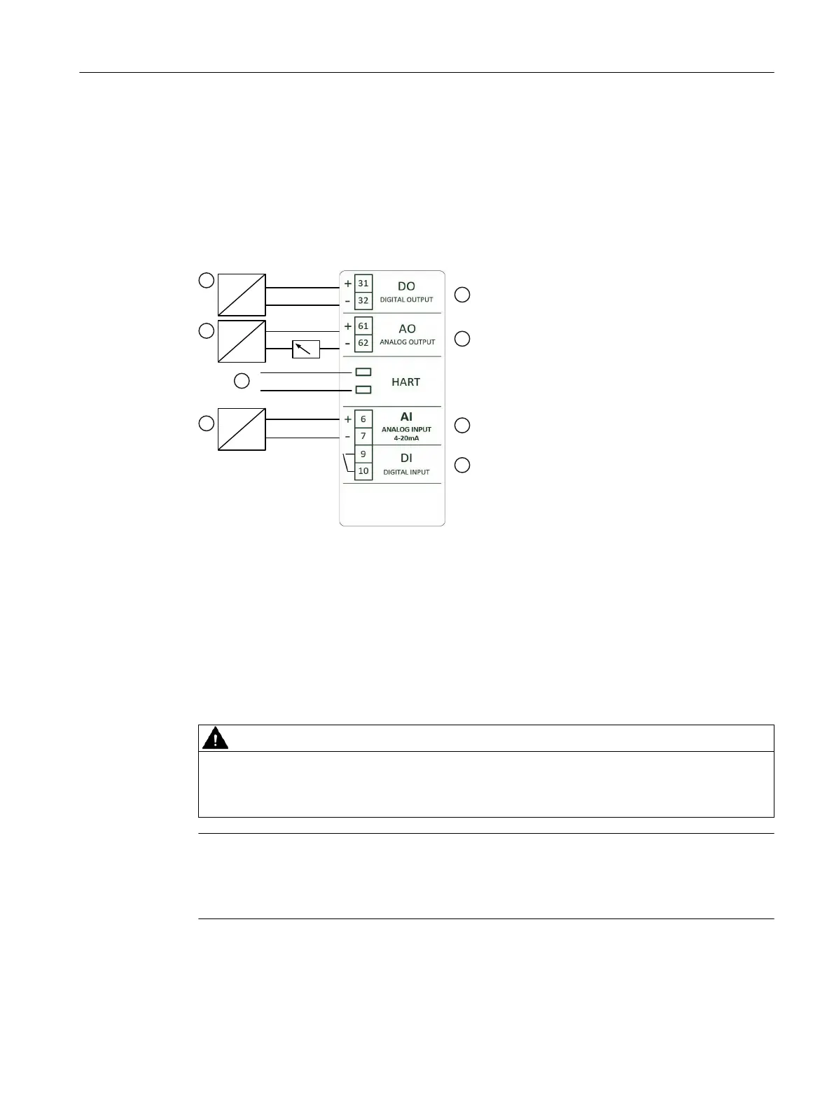
5.3 Electrical connection
① Digital input or switching amplier ⑤ Digital output
② Power source 12 to 30 V DC ⑥ Analog output of position feedback
③ HART connector ⑦ Analog input current input 4 to 20 mA
④ Signal source 4 to 20 mA ⑧ Digital input (oating contact)
Figure 5-1 Wiring diagram
5.4 Pneumatic connection
WARNING
Supply pressure PZ
For safety reasons, the supply pressure PZ can be fed after installation only if the positioner is
switched to the "NO INIT" mode when an electrical signal is available.
Note
Specications regarding air quality
Observe the specications regarding the air quality, see section "Technical specications
> Pneumatic data (Page 44)".
Connecting
5.4 Pneumatic connection
SIPART PS100
Compact Operating Instructions, 05/2021, A5E50188940-AA 29

 Loading...


