9. Keep the positioner and the mounting bracket on the actuator. Ensure that the carrier pin ④
is guided inside the pick-up bracket ②.
10.Fasten the positioner on the yoke.
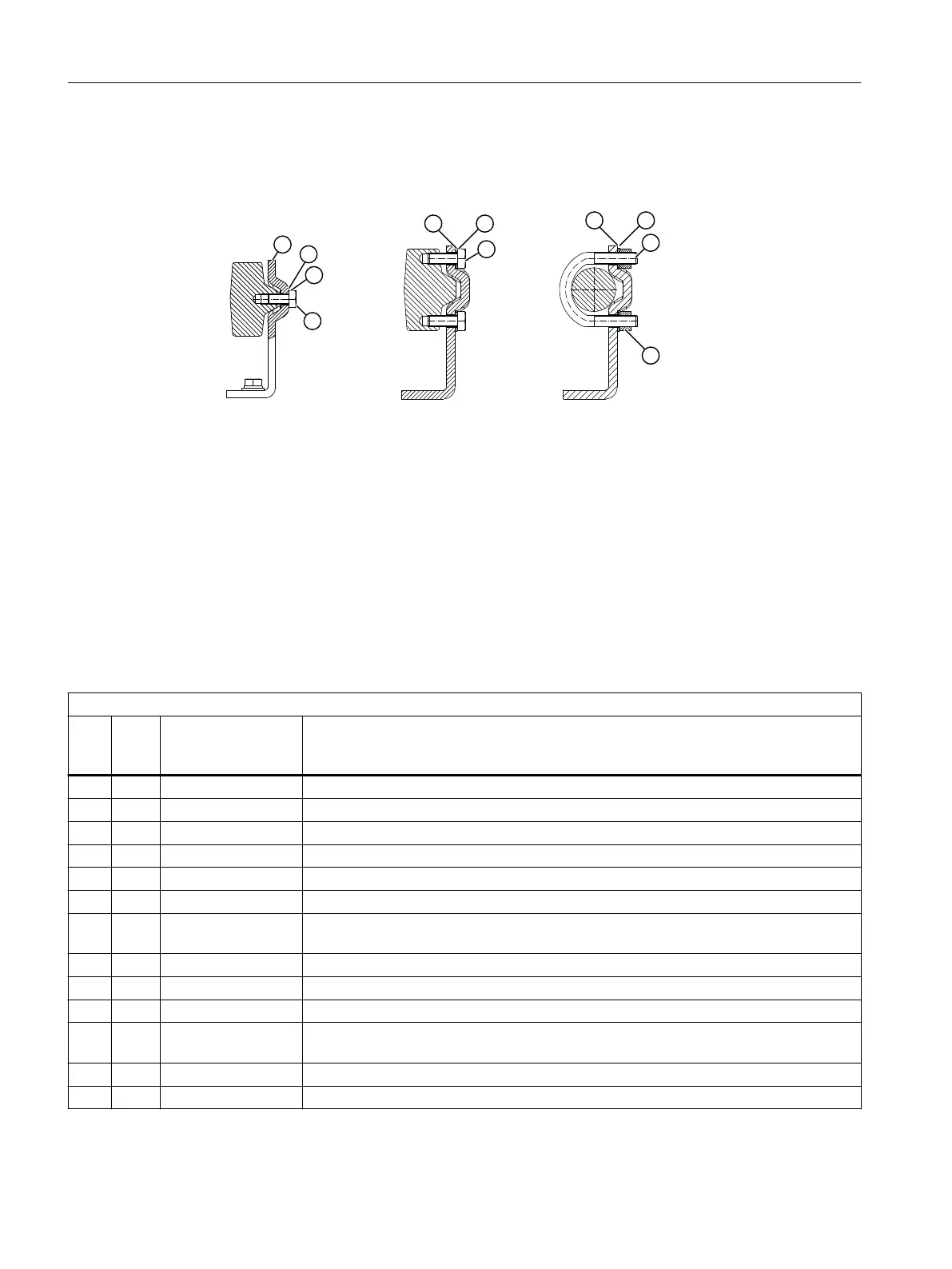
Figure 4-6 Fastening to various yoke types
4.3 Mounting to part-turn actuator
Requirements
• An actuator-specic VDI/VDE 3845 mounting console
• Mounting kit 6DR4004-8D
Procedure
"Part-turn actuator" mounting kit 6DR4004–8D
Sr.
no.
*
)
Quan
tity
Name Note
① 1 Coupling wheel Installation on positioner shaft
② 1 Carrier Installing on the actuator shaft
③ 1 Multiple plate Display of the position, consisting of scale and pointer mark
8 Scale Dierent divisions
2 Pointer mark Reference point for scale
④ Mount Actuator-specic, VDI/VDE 3845
⑤ 4 Hexagon bolt M6x12 DIN 933, torque see the section "Technical specications > Mechanical construc‐
tion (Page 45)"
⑥ 4 Lock washer S6
⑦ 1 Socket cap screw M6x16 DIN 84
⑧ 1 Washer 6.4 DIN 125
⑨ 1 Hex socket-head
screw
M4 for coupling wheel
⑩ 1 Square nut M4 for coupling wheel
1 Machinist's wrench For hexagon socket-head screw ⑨
*)
The numbers refer to the images of the description of the installation steps below.
Installing/mounting
4.3 Mounting to part-turn actuator
SIPART PS100
20 Compact Operating Instructions, 05/2021, A5E50188940-AA

 Loading...


