Note
Leakage
Besides continuous air consumption, a leakage can cause the positioner to try to compensate
the position deviation. This will result in premature wear in the entire control device.
• Check if there is leakage with "LEAKAGE TEST".
• If there is leakage, check the pneumatic connections for leaks.
Structure of pneumatic connection (Page 30)
Behavior in case of failure of the electrical auxiliary power and/or the supply pressure PZ
(Page 31)
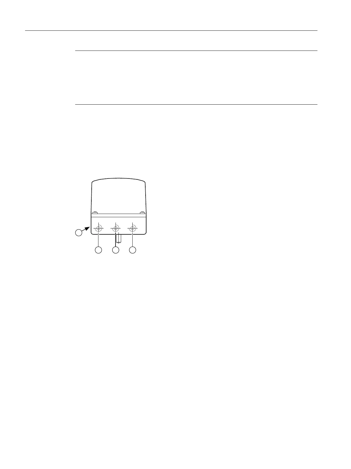
5.4.1 Structure of pneumatic connection
① Output: Actuating pressure Y2 *)
② Input: Supply pressure PZ
③ Output: Actuating pressure Y1
④ Exhaust air outlet with sound absorber, thread G¼
*) for double-acting actuators
Figure 5-2 Pneumatic connection, example
Connecting
5.4 Pneumatic connection
SIPART PS100
30 Compact Operating Instructions, 05/2021, A5E50188940-AA
 Loading...


