27SIPROTEC 4/5, Injection Unit 7XT71, Product Information
C53000-B1174-C128-7, Edition 09.2016
✧ Adjust the desired frequency at DIP switches S1.1 to S1.4 according to figure 9-
2.
✧ Reinstall the device as described in Chapter 9.2.2.
✧ If you have disconnected the cables from the terminal strip, reconnect the
cables to the screw terminals. Observe the correct wiring when doing so.
✧ Take the device into operation.
✧ Check the test value for the Injection Unit 7XT71 at the 7UM62/7UM85.
✧ If the test values are correct, the frequency setting is finished.
✧ Note the new frequency on the sticker affixed to the device.
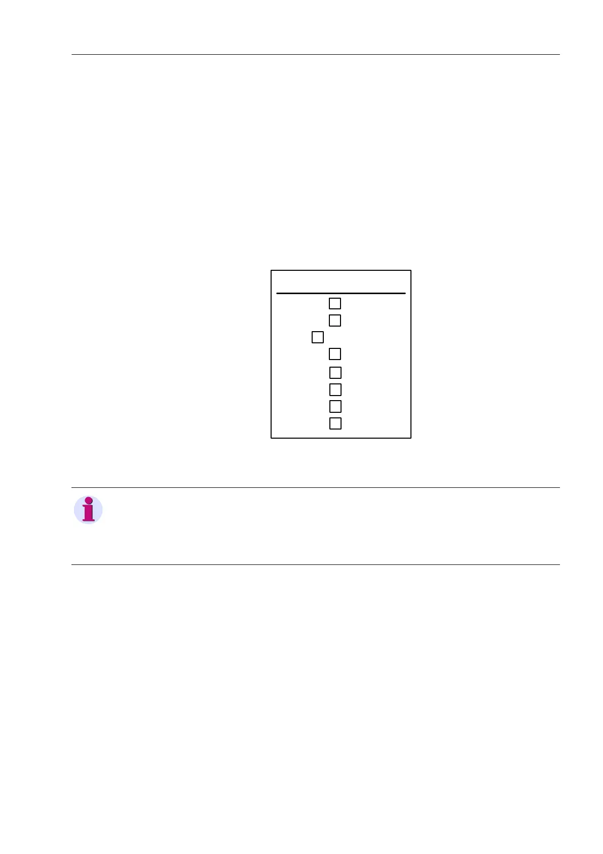
Fig. 9-4 Sticker for Adjusted Frequency
9.3 LEDs
The Injection Unit 7XT71 features 2 LEDs on the front cover and 2 LEDs on the
back plate. The LEDs with the same designation are switched in parallel so that the
device status is visible for both the surface-mounting and the flush-mounting ver-
sion.
Umpolfrequenz /
Frequency of polarity reversal
0,5 Hz
X
1,0 Hz
1,5 Hz
2,0 Hz
2,5 Hz
3,0 Hz
3,5 Hz
4,0 Hz
NOTE
If the 7UM62/7UM85 does not show any correct values yet, repeat the frequency
setting at the Injection Unit 7XT71 until the values approximate the required oper-
ating conditions.
 Loading...