39SIPROTEC 4/5, Vorschaltgerät 7XT71, Produktinformation
C53000-B1174-C128-7, Ausgabestand 09.2016
14 Anschlusspläne
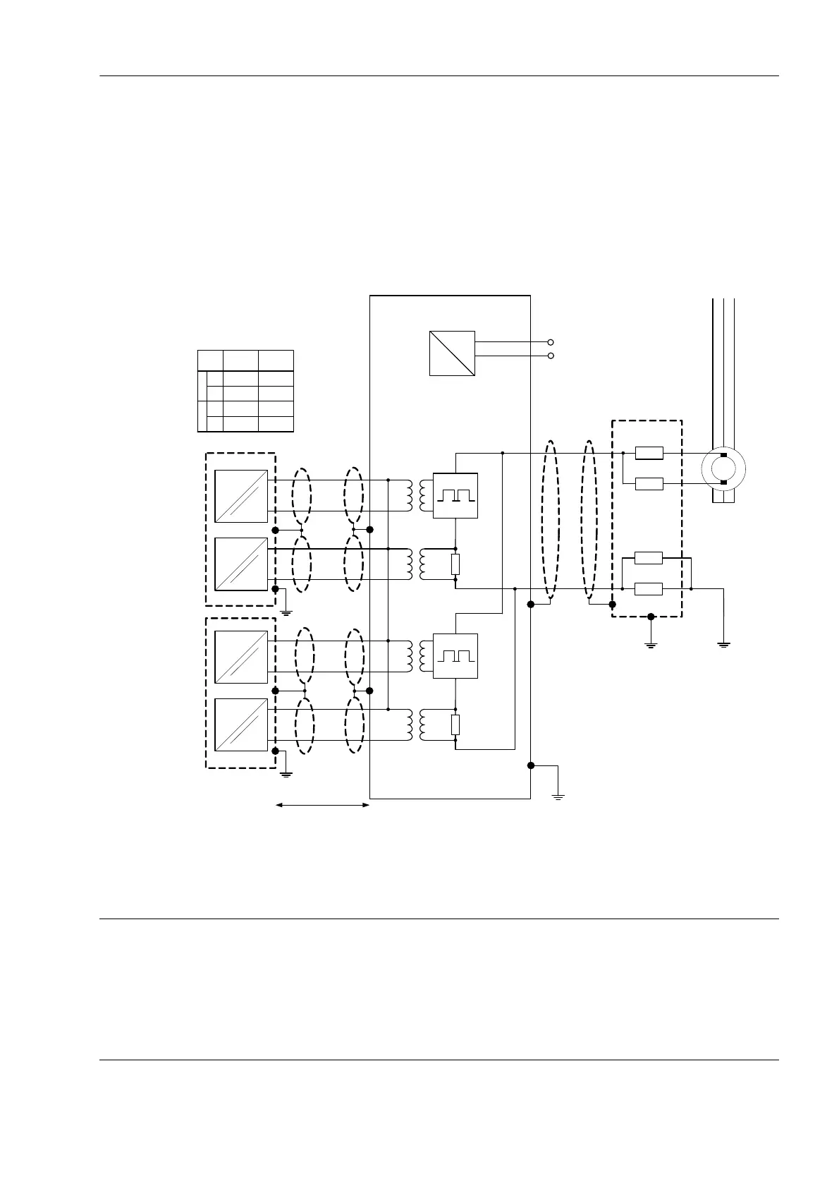
Bild 14-1 Anschlussplan für Erregerspannungen < DC 850 V
Abbildung 1-1: Anschlußplan für Erregerspannungen < DC 850 V
Figure 1-1: Connection Diagram for excitation voltages < DC 850 V
7UMxx
7UMxx
7XR6004
L1 L2 L3
1
2
7
11
9
13
8
10
12
14
~
=
17
18
Erde der Generatorwelle
Rotor Ground
MU
1
MU
2
MU
1
MU
2
A11A6
A3
B14
B11
B18
A
B
C
D
A
B
C
D
U
Mess
V
Meas
U
Mess
V
Meas
U
Steuer
V
Control
U
Steuer
V
Control
Leitungslänge < 10 m
cable lenght < 10 m (30 feet)
+UH UL 1
-UH UL2
DC AC
20 kΩ
20 kΩ
20 kΩ
20 kΩ
7XT71
A
B
C
D
K13
K14
K15
K16
B13
C3
B14
C4
7UM62
7UM85
(IO210 )
Schutzger ätanschlusse
Protection relay connections
MU1MU2
ACHTUNG
Die Spannung zwischen Klemme 1 und Klemme 2 (und auch zur Erdung) darf
AC 300 V nicht überschreiten.
Nichtbeachtung kann zu Sachschäden führen.
✧ Wenden Sie geeignete Schutzmaßnahmen an.
 Loading...