32 SIPROTEC 7SJ81/7SK81 V4.7, Produktinformation
E50417-K1150-C462-A2, Ausgabestand 02.2012
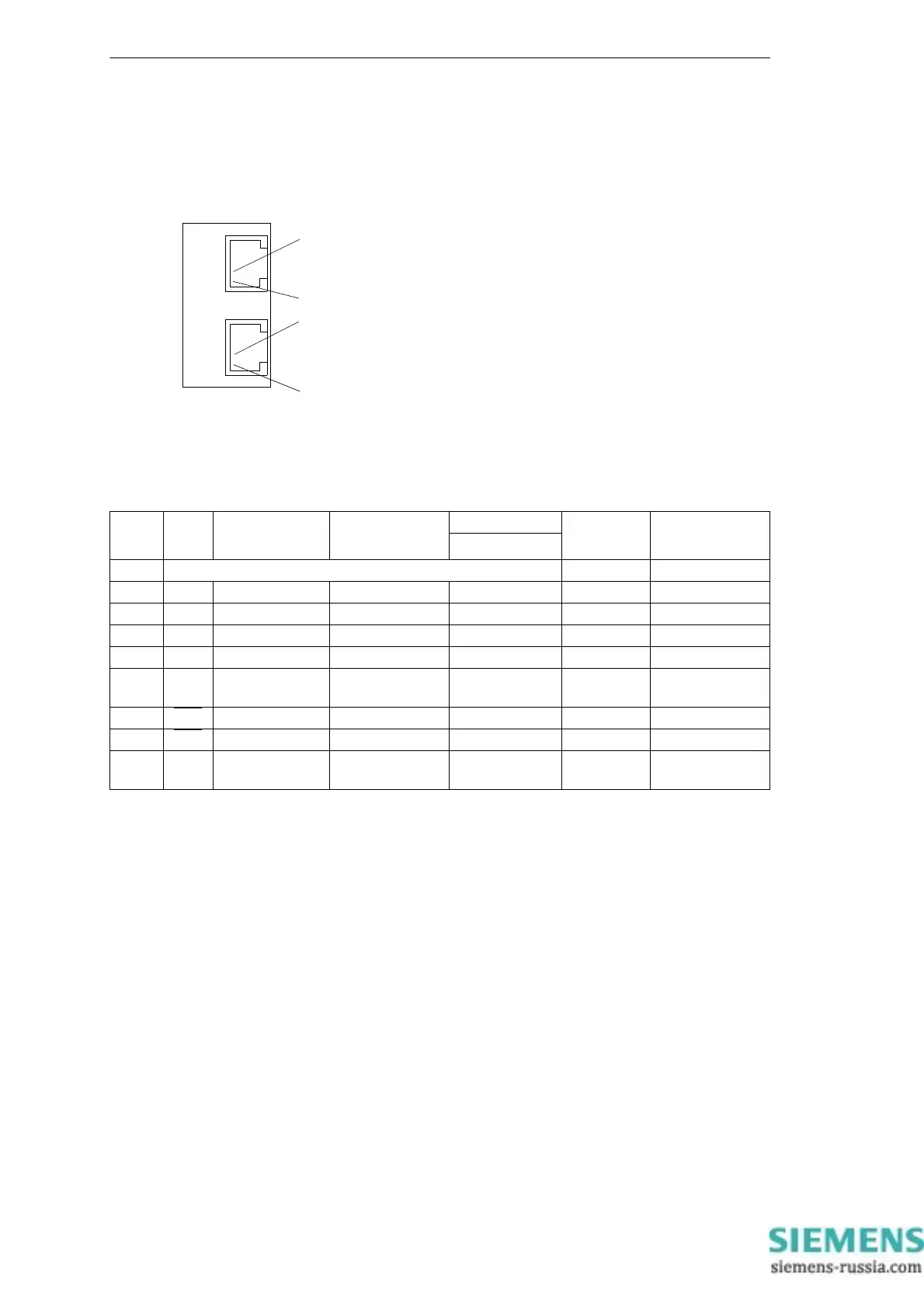
IEC 60870-5-103 Schnittstelle redundant
Für die drahtgebundene redundante T103-Schnittstelle dienen 8-polige
RJ45-Buchsen als Anschlüsse.
Bild 13 T103-Schnittstelle redundant
Belegung der Buchsen Port A und B
1)
Pin 7 trägt auch bei Betrieb als RS485-Schnittstelle das Signal RTS mit
RS232-Pegel. Pin 7 darf deshalb nicht angeschlossen werden!
USB-DIGSI-Schnittstelle
Über die USB-Schnittstelle können Sie eine Verbindung zwischen dem
Schutzgerät und Ihrem PC herstellen. Für die Kommunikation wird der
Microsoft Windows USB Treiber verwendet, der zusammen mit DIGSI (ab
Version V4.82) installiert wird. Die Schnittstelle wird als virtueller serieller
COM Port eingerichtet. Empfohlen wird hierbei die Verwendung han-
delsüblicher USB-Kabel mit einer maximalen Länge von 5 m.
1
2
RJ45-Buchse
T103 - redundant
Ch1 Ch2
1
2
Pin-Nr. RS232 RS485 Profibus DP,
RS485
Modbus RS485 Ethernet
Port A und B
IEC 60870-5-103
redundant
DNP3.0 RS485
1 Schirm (mit Schirmkragen elektrisch verbunden) Tx+ B/B’ (RxD/TxD-P)
2 RxD – – – Tx– A/A’ (RxD/TxD-N)
3 TxD A/A’ (RxD/TxD-N) B/B’ (RxD/TxD-P) A Rx+ –
4 – – CNTR-A (TTL) RTS (TTL Pegel) – –
5 GND C/C’ (GND) C/C’ (GND) GND1 – –
6 – – +5 V (belastbar
mit <100 mA)
VCC1 Rx– –
7RTS
–
1)
––––
8CTS
B/B’ (RxD/TxD-P) A/A’ (RxD/TxD-N) B – –
9 – – – – nicht vorhan-
den
nicht vorhanden

 Loading...


