31SIPROTEC 7SJ81/7SK81 V4.70, Product Information
E50417-K1150-C462-A2, Edition 02.2012
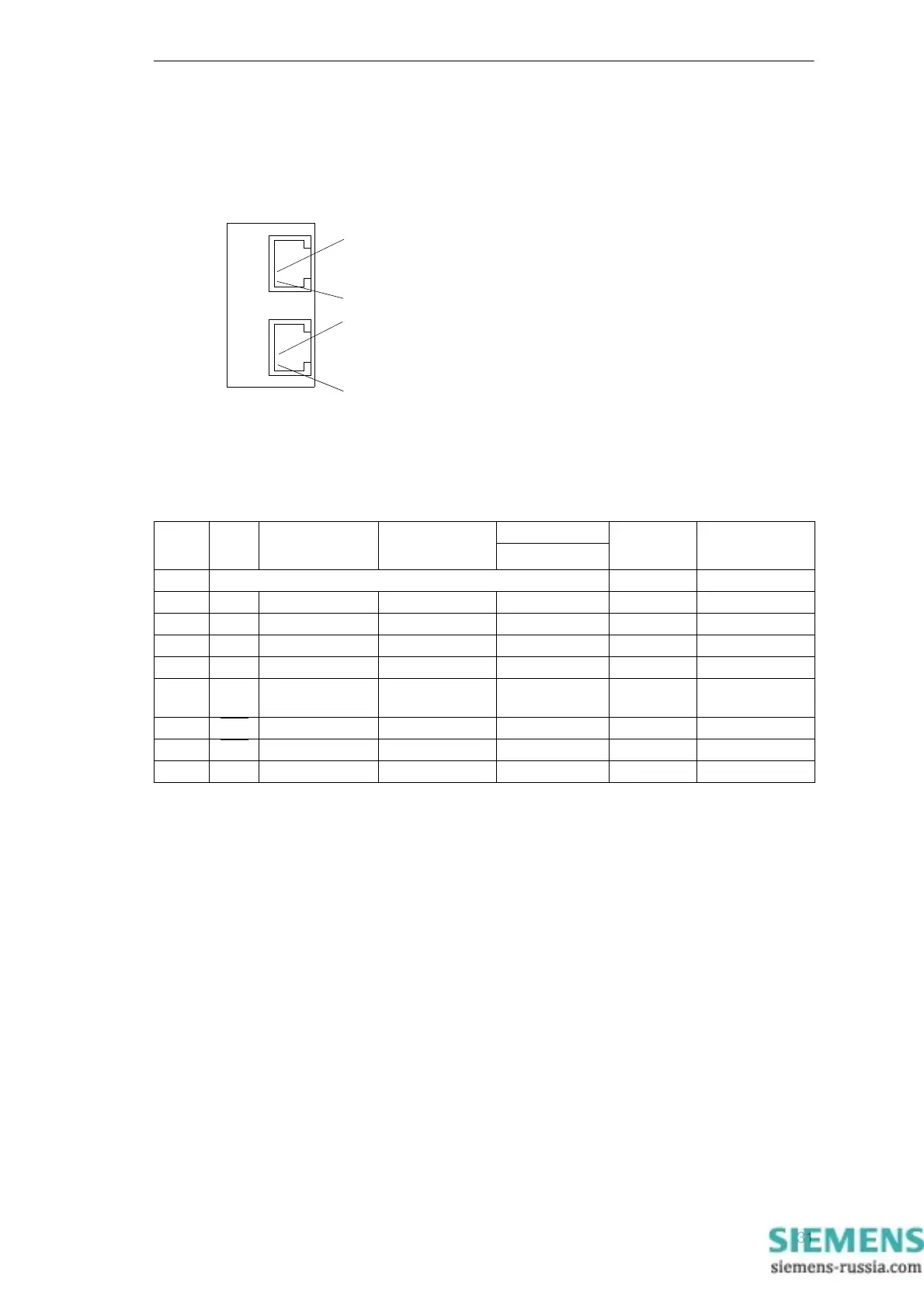
Connections to IEC 60870-5-103 Redundant
8-pin RJ45 socket connectors are provided for electrical communication
interface T103 redundant.
Figure 13 Interface T103 redundant
Assignment of the port A and B sockets
1)
Pin 7 also carries the RTS signal with RS 232 level when operated as
RS 485 interface. Pin 7 must therefore not be connected!
USB-DIGSI-Interface
The USB interface can be used to establish a connection between the
protection device and your PC. For the communication, the Microsoft
Windows USB driver is used which is installed together with DIGSI (as of
version V4.82). The interface is installed as a virtual serial COM port. We
recommend the use of standard USB cables with a maximum length of
5 m/16 ft.
1
2
RJ45 socket
T103 - redundant
Ch1 Ch2
1
2
Pin-No. RS232 RS 485 Profibus DP,
RS 485
Modbus RS 485 Ethernet
Port A and B
IEC 60870-5-103
redundant
DNP3.0 RS 485
1 Shield (electrically connected with shield shroud) Tx+ B/B’ (RxD/TxD-P)
2 RxD – – – Tx– A/A’ (RxD/TxD-N)
3 TxD A/A’ (RxD/TxD-N) B/B’ (RxD/TxD-P) A Rx+ –
4 – – CNTR-A (TTL) RTS (TTL Pegel) – –
5 GND C/C’ (GND) C/C’ (GND) GND1 – –
6 – – +5 V (max load
<100 mA)
VCC1 Rx– –
7RTS
–
1)
––––
8CTSB/B’ (RxD/TxD-P) A/A’ (RxD/TxD-N) B – –
9 – – – – not available not available

 Loading...


