2 Functions
306
7UT613/63x Manual
C53000-G1176-C160-2
In addition to the measured and calculated values at the measuring locations, mea-
sured values are output at the sides
of the main protected object. This makes if pos-
sible to obtain the data relevant for the protected object, even if they are fed to the pro-
tected object from several measuring locations, as for example the higher voltage side
(S1) of the transformer. Also, relative values are always referred to a specific side of
the protected object. A current which does not flow into the object from 2 measuring
locations (e. g. a current flowing from one busbar through M1 and M2 to the other
busbar) is theoretically zero because no current flows into the protected object.
Table 2-13 summarizes the operational measured values that are assigned to the
sides. Depending on the device’s order number, connection type, topology and pro-
tection functions configured, only a part of the magnitudes listed there is available. The
table does not apply to the single-phase busbar protection, since no sides are defined
there.
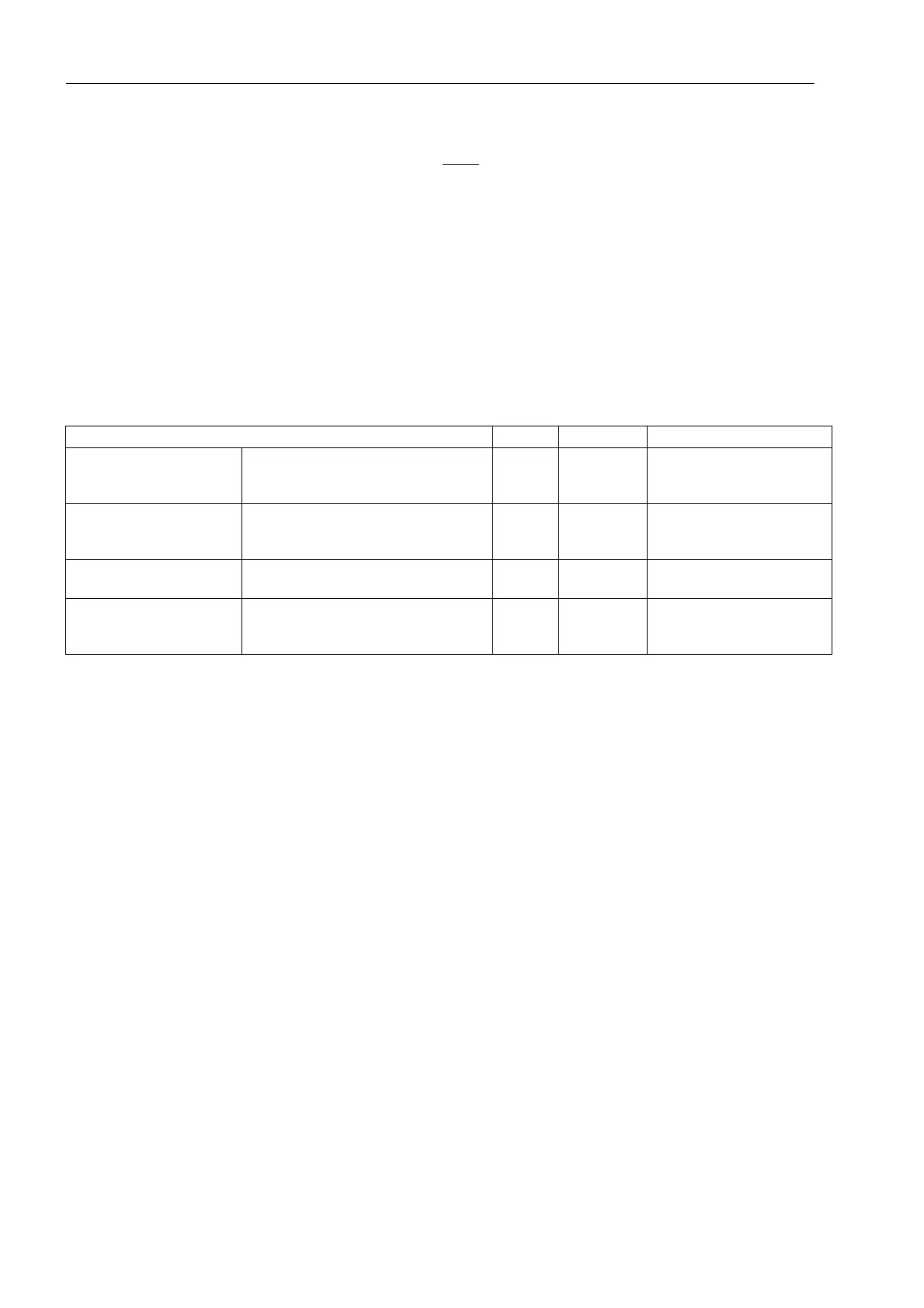
Table 2-13 Operational measured values (magnitudes) of the sides
1)
only for 3-phase objects, also for single-phase transformers
2)
only for 3-phase objects, not for single-phase transformers
3)
only for 7UT635
The phase angles are listed separately in Table 2-14. The reference value for 3-phase
objects is the current I
L1M1
(current in phase L1 at measuring location M1), which has
thus a phase angle = 0°. With 1-phase busbar protection, the current I
1
has the phase
angle 0°, i.e. it is the reference value.
Depending on the device’s order number, connection type, topology and protection
functions configured, only a part of the phase angles listed there is available.
The phase angles are indicated in degrees. Since further processing of such values
(in CFC or when transmitted through serial interfaces) requires values without dimen-
sion, arbitrary references have been chosen, which are contained in Table 2-14 in the
column „% conversion“.
Measured Values Primary Secondary % referred to
IL1S1, IL2S1, IL3S1
IL1S2, IL2S2, IL3S2
IL1S3, IL2S3, IL3S3
1)
Phase currents flowing in from the sides
S1 to S3
1)
A; kA — Rated operating current of
the respective side
I1S1, I2S1, 3I0S1
I1S2, I2S2, 3I0S2
I1S3, I2S3, 3I0S3
2)
Positive, negative and zero sequence
component of the currents at the sides
S1 to S3
2)
A; kA — Rated operating current of
the respective side
IL1S4, IL2S4, IL3S4
IL1S5, IL2S5, IL3S5
1)
3)
Phase currents flowing in from the sides
S4 to S5
1)
3)
A; kA — Rated operating current of
the respective side
I1S4, I2S4, 3I0S4
I1S5, I2S5, 3I0S5
2)
3)
Positive, negative and zero sequence
component of the currents at the sides
S4 to S5
2)
3)
A; kA — Rated operating current of
the respective side
 Loading...


