SIRIUS 3RT2 contactors/contactor assemblies
2.6 Connection
SIRIUS Innovations
System Manual, 01/2011, A8E56203870002-03
153
2.6 Connection
Connection systems
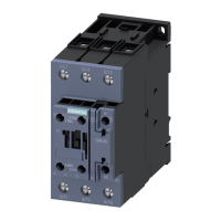
The SIRIUS contactors are available with the following connection types:
● Screw-type connection system
● Spring-loaded connection system
● Ring cable lug connection system
● Solder pin connection (only possible for size S00, in conjunction with a solder pin
adapter)
Terminal designations
Terminal Designation
A1 Coil terminal +
A2 Coil terminal -
L1, L2, L3 Contactor's main circuit terminal to the power network
T1, T2, T3 Contactor's main circuit terminal to the load/motor connection
13. 14 Auxiliary contact, closing
21. 22 Auxiliary contact, opening
The auxiliary/control contacts have a two-digit designation:
● First digit: Consecutive number of the auxiliary contacts (sequence number).
● Second digit: Task of the relevant auxiliary contact (function number).
For example, 1-2 for NC contact or 3-4 for NO contact
Terminal designations of the auxiliary contacts
The terminal designations as per DIN EN 50012 apply to size S00 contactors with an
integrated auxiliary (NO) contact. Auxiliary contacts are fitted and arranged on size S0
contactors (integrated in the basic device) in accordance with the terminal designations
contained in DIN EN 50012.
Additionally, for sizes S00 and S0, complete devices with permanently mounted auxiliary
switch blocks (2 NO contacts + 2 NC contacts in accordance with DIN EN 50012) are
available.
Coil terminals
Size S00 and S0 contactors feature a coil terminal on the front. An adapter
(3RT2926-4R./. coil terminal module) can be used to move the coil terminal up or down on
size S0 contactors (compatible with 3RT102).
Reference
More information ... Can be found in the chapter titled ...
About the coil terminal module and how to mount
it on a 3RT20 contactor (size S0)
Coil terminal module (Page 195)

 Loading...


