4
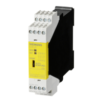
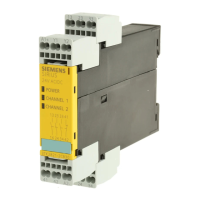
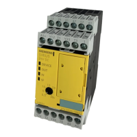
SIRIUS
Safety Relays
3TK2826-....1/2/4
DIN EN 60947-5-1 (08.00)
EN 13849/EN 954-1/IEC 61508
Operating Instructions
Order No.: 3ZX1012-0TK28-4EA1
English
The devices must be installed in switchgear cabinets with an adequate
degree of protection which takes the ambient conditions into account.
The products described here were developed to assume safety-related functions
within a system or machine. A complete safety-related system usually includes
sensors, evaluation units, signaling devices and concepts for ensuring safe
switch-off. The manufacturer of the system or machine is responsible for ensur-
ing the correct overall functionality. Siemens AG, its branch offices and associ-
ated companies (hereinafter referred to as
"Siemens") cannot guarantee all
properties of a system or machine not designed by Siemens.
Siemens can also not assume liability for recommendations given or implied by
the following description. No new guarantee/warranty or liability claims in excess
of the general terms and conditions of Siemens can be deduced from the follow-
ing description.
The 3TK2826 safety relay can be used in EMERGENCY STOP mechanisms
according to EN 418 and in safety circuits according to EN 60 204-1 (11.98), e. g.
with movable guards and protective doors or with contact-free protection devices
according to IEC 61496-1 (06.98). The device has instantaneous release circuits
(stop category 0) and release circuits with a time-delayed trip (stop category 1).
Depending on the outer wiring category 4 according to DIN EN 954-1, SIL3 accor-
ding to IEC 61 508 or PL"e" according to EN 13849 must be achieved.
3TK2826-.BB41/2/4 only
Use a power supply unit that complies with
IEC 60536 safety class III (SELV or PELV)!
* 3TK2826-.BB41/2/4 only
** 3TK2826-.CW31/2/4 only
Figures
Figure Ia/Ib Terminal designation / dimension drawing (dimensions in mm)
Figure IIa/IIb Installation/connection example
Note:
Adequate protective wiring is necessary for capacitive and inductive loads.
Read and understand these instructions before installing,
operating, or maintaining the equipment.
DANGER
Hazardous voltage.
Will cause death or serious injury.
Turn off and lock out all power supplying this device before
working on this device..
CAUTION
Reliable functioning of the equipment is only ensured with certified
components.
Important note
Areas of application
Terminal designation Signal description
A1 +/L
A2 –/N
13/14; 23/24; Release circuit (FK) relay, NO, instantaneous
31/32 Signaling circuit (MK) relay, NC (FK status),
instantaneous
47/48; 57/58 Release circuit (FK) relay, NO, time-delayed
61/62 Signaling circuit (MK) relay, NC (FK status), time-
delayed
74 * MK electronic 24 V DC; return circuit fault (RF)
84 * MK electronic 24 V DC; (sensor status)
73/74 ** MK relay NO, return circuit fault (RF)
T1, T2 Test outputs
T3 Sensor supply 24 V DC
1 Cascading input / operational switching
Y12, Y22 Sensor input channel 1, channel 2
Y33 Start button (start in the case of a rising edge or a
falling edge)
Y34 Return circuit (RF)
!
LEDs Color Meaning
DEVICE
OFF No power
Green Device ready for operation
Green,
flashing
Self-test during restart
Yellow Configuration mode DIP switches
Yellow,
flashing
Configuration error or configuration mode
delay time
Green/yellow,
flashing
Delay time changed
Red Device defective
OUT
OFF Output inactive
Green Output active
Green,
flashing
RF (return circuit) not closed when
starting condition has been fulfilled
IN
OFF Input inactive
Green Input active
Green,
flashing
Fault recognized (e.g. cross over at the
input, sensor simultaneity not fulfilled)
SF
OFF No general fault (SF)
Red General fault (e.g. wiring fault, cross over,
wire break during safety shut-off mat
operation, configuration error)
Red, flashing
General fault (RF fault, simultaneity
condition not fulfilled)
Technical Data
Rated operating voltage 3TK2826-*BB41/2/4 24 V DC + 20 %/– 15 %
Rated operating voltage 3TK2826-*CW31/2/4 24 V - 240 V AC/DC +/– 10 %
Further
Information:
German: 3TK2890-1A
English: 3TK2890-1B
Meaning of the DIP switches
DIP switch factory configuration
Without cross over detection
1 NC + 1 NO - analysis
2 x 1 channel
Debounce time for sensor inputs 50 ms
Sensor input auto-start
Cascading input auto-start
With start-up testing
Automatic start after power failure*
With cross over detection
2 NC - analysis
1 x 2 channels
Debounce time for sensor inputs 10ms
Sensor input monitored start
Cascading input monitored start
Without start-up testing
Without automatic start after power failure
87
654321
ON
*(not pemissible in connection with start-up testing)
DIP switch setting in safety shut-off mat operation
87
6
5
4321
ON
Debounce time for sensor inputs 50 ms
Sensor input auto-start
Cascading input auto-start
With start-up testing
Automatic start after power failure *
Debounce time for sensor inputs 10 ms
Sensor input monitored start
Cascading input monitored start
Without start-up testing
Without automatic start after power failure
*(not pemissible in connection with start-up testing)
}
Safety shut-off mat operation
 Loading...