TC65 Terminal Hardware Interface Description
Confidential / Released
s
TC65 Terminal_HD_V02.000b Page 22 of 65 2007-02-19
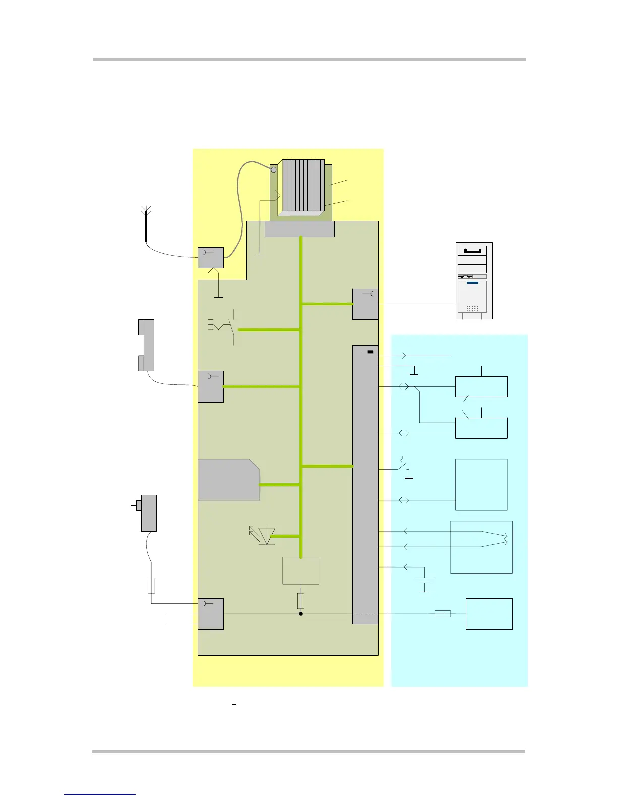
3.2 Block Diagram
Figure 3 shows a block diagram of a sample configuration that incorporates a TC65
Terminal and typical accessories.
Figure 3: Block diagram
I2C device
SPI device
2x Analog
measurements
(balanced)
Power Supply
Unit
IO connector
Application
3.0V Backup Battery
RS232
RS232
80 pin B2B
RF
Audio
SIM
Power
SMA
(female)
Step Down
DC/DC
Converter
GSM
Module
TC65
Heat Sink
RF Cable
SMA-Hirose
Contact
spring
Contact
spring
Votronic
Handset
or other
audio equipment
100V...240V
AC Adapter
or
DC Supply
TC65 Terminal
TC65T Mainboard
Antenna
VDD (2.9V)
or
On/Off
Key
8V...30V
In or Out
sensors,
relay unit,
switches,
etc.
10xGPIO
ON/OFF
Ignition
Emergency-off
VDD
VDD
8V...30V
1)
1)
1) Fast acting fuse I>0.8A , (0.8...1.5 A
2
s) is recommended for 24V vehicle supply only.
 Loading...