TC65 Terminal Hardware Interface Description
Confidential / Released
s
TC65 Terminal_HD_V02.000b Page 27 of 65 2007-02-19
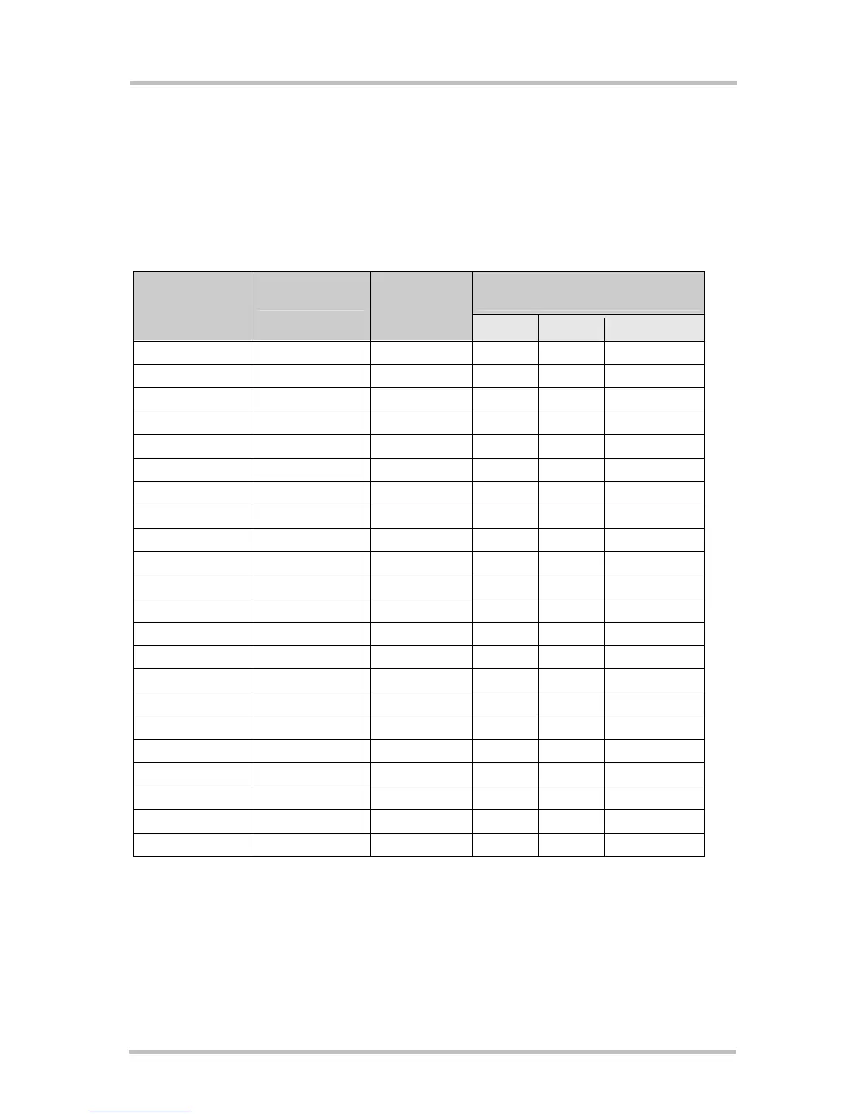
3.5.5 Signal States after Startup
Table 9 describes the various states each interface pin passes through after startup and
during operation.
The state of several pins will change again once the respective interface is activated or
configured by AT command.
Table 9: Signal states
Active state after configuration by
AT command
Signal name Undefined state
during startup
Defined state
after
initialization
GPIO SPI I
2
C
RXD O, L O, L
TXD I I
CTS O, H O, H
RTS I I
DTR I I
DCD O, H O, L
DSR O, H O, L
RING O, L O, L
SPIDI I Tristate I Tristate
SPICS I O, H O, L Tristate
I2CDAT_SPIDO I Tristate O, L/H IO
I2CCLK_SPICLK I Tristate O, L/H O, OD
IO1 I, PU Tristate IO
IO2 I, PU Tristate IO
IO3 I, PU Tristate IO
IO4 I, PD Tristate IO
IO5 O, L Tristate IO
IO6 I Tristate IO
IO7 I Tristate IO
IO8 O, L Tristate IO
IO9 I Tristate IO
IO10 I Tristate IO
Abbreviations used in
Table 9:
L = Low level
H = High level
L/H = Low or high level
I = Input
O = Output
OD = Open Drain
PD = Pull down with min +15µA and max. +100µA
PU = Pull up with min -15µA and max. -100µA
 Loading...