TC65 Terminal Hardware Interface Description
Confidential / Released
s
TC65 Terminal_HD_V02.000b Page 55 of 65 19.02.2007
5.6 Characteristics of the Audio Interface
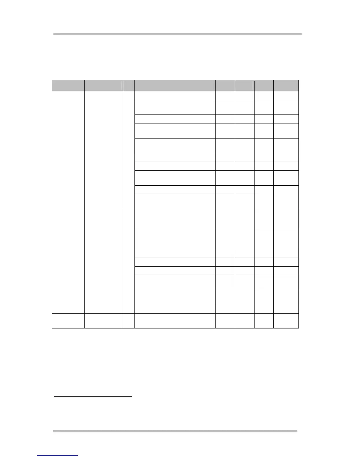
Table 31: Characteristics of the audio interface
Function Signal name IO Parameter Min. Typ. Max. Unit
DC (no load) at MICP 5.3 5.4 5.6 V
DC at MICP
in POWER DOWN
0V
V
DC (no load) at MICN 0 V
DC Resistance differential
MICN, MICP (balanced)
4.6 4.7 4.8 kOhm
Impedance
Zi (balanced)
3.9 4.0 4.1 kOhm
Input level Uimax 0.6 V
PP
Restricted Input level Uires
7
1.6 V
PP
Gain range
6 dB steps
0 42 dB
Frequency Range 200 3900 Hz
Microphone MICP, MICN
I
fine scaling by DSP
(inCalibrate)
-∞ 0 dB
Impedance
(balanced)
8 Ohm
AC output level UO
Gain = 0dB @ 3.14 dBm0
no load
5.97 V
PP
Gain range -18 0 dB
Gain accuracy 0.8 dB
Frequency area 200 3900 Hz
DC Offset
(balanced)
100 mV
Attenuation distortion
for 200...3900Hz
1 dB
Earpiece EPP, EPN
O
Out-of-band discrimination 70 dB
LEAudio
Length of Audio (Handset)
cable
3 m
Unless otherwise stated, all specified values are valid for gain setting (gs) 0dB and 1kHz
test signal.
gs = 0dB means audio mode = 5, inBbcGain= 0, inCalibrate = 32767, outBbcGain = 0,
OutCalibrate = 16384, sideTone = 0.
The electrical characteristics of the voiceband part depend on the current audio mode
selected by the AT command AT^SNFS. See
Table 11: Audio modes.
The audio modes 4 and 5 can be adjusted by parameters. Each audio mode is assigned a
separate parameter set.
7
At least one of the following conditions has to be met in order to exceed U
imax
= 0.6 Vpp up to the restricted
voltage limit U
ires
= 1.6Vpp:
- A call is established
- The module is not in power down and the AT command “AT^SNFM=,1” was executed.
If 0.6Vpp is exceeded under any other condition undervoltage shutdown may be caused.
 Loading...