EasyManua.ls Logo

SIGMATEK CCP 531 - User Manual

SIGMATEK CCP 531
30 pages
Print Icon
To Next Page IconTo Next Page
Loading...
C-DIAS PROCESSOR MODULE CCP 531
12.04.2017 Page 1
C-DIAS Processor Module CCP 531
The CCP 531 processor module runs the control program and
thereby represents an essential component of an automation
system. The internal DC/DC converter powers all modules on a
C-DIAS module carrier.
The CAN bus, an Ethernet interface or the USB device (Mini
USB) can be used as the online interface connection.
A 7-segment display and 2 status LEDs provide information on
the actual status of the CPU.
For program updates, the integrated USB Host interface can be
used (USB stick, keyboard). With help from the exchangeable
SD card, the entire control program can be easily exchanged.
The CCP 531 processor module is designed to be mounted in
the control cabinet.
Compatibility
Completely PC-compatible. The CCP 531 works with standard PC BIOS and therefore no
SIGMATEK-specific BIOS is needed; the LASAL operating system in provided.
Question and Answer IconNeed help?

Do you have a question about the SIGMATEK CCP 531 and is the answer not in the manual?

SIGMATEK CCP 531 Specifications

General IconGeneral
Power supply24 V DC
Operating temperature0 to 50 °C
Operating temperature range0 to 50 °C
Protection classIP20
Operating systemLinux
InterfacesEthernet, USB, RS232
Input voltage range18 V to 30 V DC

Summary

C-DIAS Processor Module Overview

Technical Data

Performance Specifications

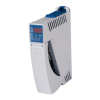
Details on processor, clock frequency, memory, and interfaces.

Electrical Requirements

Connector Layout Diagram

microSD Card Management

Display Functionality and Interpretation

CAN Bus Configuration

Station Number Assignment on CAN Bus

Procedure for assigning a unique station number on the CAN bus.

Data Transfer Rate and Bus Length

Configuring baud rate and its relation to bus length.

Process Module Configuration Procedures

Initiating Configuration Mode

How to initiate configuration via the SET button during boot.

Navigating and Modifying Settings

Using the SET button for menu navigation and parameter changes.

Saving or Discarding Configuration Changes

Procedures for saving or discarding changes using SET/RESET buttons.

Network Parameter Display Interpretation

CAN Bus Termination Requirements

Wiring and Mounting Instructions

Essential Earth Connection Requirements

Importance and methods for creating a low-ohm earth connection.

Electrical Safety and Signal Integrity

ESD Protection and Safe Handling Practices

Measures for preventing electrostatic discharge and safe handling.

System Boot Checkpoint Interpretation

Status and Error Messages: Core Operations

Normal Operation Status Messages

Meaning of RUN RAM, RUN ROM, and RUNTIME status messages.

Pointer and Checksum Error Diagnosis

Causes and solutions for POINTER and CHKSUM errors.

Status and Error Messages: Watchdog & Programming

Status and Error Messages: Program Execution

Program Interruption and Breakpoint Errors

Errors related to breakpoints, interrupts, and single-step mode.

Module Compatibility and Memory Errors

Issues with module compatibility and memory allocation.

Status and Error Messages: Bus & Operating System

Status and Error Messages: Application & Runtime

Application Loading, Saving, and Memory Errors

Errors in application loading, saving, and memory access.

Runtime Limit Exceeded Error Conditions

Issues when real-time or background runtime limits are exceeded.

Status and Error Messages: SRAM & User-Defined

Status and Error Messages: Linking & System Operations

Application Exceptions and Data Handling

SRAM Behavior and Best Practices

Related product manuals