Do you have a question about the SIGMATEK AM 441 and is the answer not in the manual?
Defines the intended audience and purpose of the operating manual.
Lists or refers to other essential documentation relevant to the product.
Details the items included in the product package.
Explains the meaning of standard symbols used for warnings and information.
States limitations of liability and disclaims warranties for the manual's content.
Provides overall safety guidelines and compliance information for safe operation.
Discusses software requirements and available training for product configuration and use.
Lists relevant European Union directives and EU Conformity Declarations for the product.
Specifies technical details for analog input channels and potentiometer input configurations.
Details the electrical and performance specifications for the module's reference output.
Outlines the technical specifications for the module's analog output channels.
Covers voltage supply requirements and current consumption for the S-DIAS bus.
Contains general product information such as article number, standard compliance, and approvals.
Specifies operating and storage conditions like temperature, humidity, EMC, and vibration resistance.
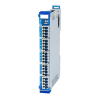
Describes the function and status indication of the module's LEDs.
Details specifications for connecting wires and terminals, including conductor cross-sections.
Information regarding the label field and compatible printers for marking.
Illustrates a typical wiring example for connecting the module.
Provides important notes and best practices for correct and error-free wiring.
Explains different methods for connecting voltage sources and potentiometers to the inputs.
Instructs users to verify that all delivered components are present and intact before installation.
Details the procedure for mounting the module on a DIN-rail within a control cabinet.
Describes the speed mode for analog inputs, enabling high sampling rates and continuous measurement.
Details the time-offset mode for analog inputs and outputs, allowing precise timing of sampling and output.
Specifies supported cycle times below 1 millisecond, measured in microseconds.
Specifies supported cycle times of 1 millisecond or greater, measured in milliseconds.
Details address allocation for hardware class communication with older firmware versions (V01.00-V01.20).
Details address allocation for hardware class communication with newer firmware versions (≥ V02.00).
Mentions that the product is designed for low-maintenance operation.
Provides instructions on handling defects and contacting support for repairs.
Describes the general properties, status, and configuration of the AM441 hardware class.
Explains the communication interfaces, alarm handling, and data properties of the hardware class.
| Product type | Control Unit |
|---|---|
| Supply voltage | 24 V DC |
| Processor | Intel Atom |
| Clock Speed | 1.6 GHz |
| Ethernet Ports | 2 |
| USB Ports | 2 |
| Interfaces | Ethernet, USB, CAN |
| Operating System | Linux |
| Operating Temperature | 0°C to 55°C |
| Series | AM 400 Series |