Do you have a question about the SIGMATEK MDD 121-1 and is the answer not in the manual?
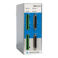
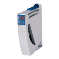
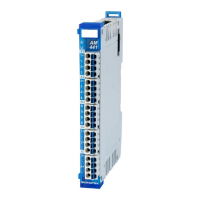
Overview of the servo system components including power supply and axis modules.
Explains the content and scope of the manual for the MDD 121-1 axis module.
Defines important symbols and their meanings used throughout the document for safety and warnings.
Provides critical safety guidelines and warnings for installation, setup, and operation of the servo drive system.
Details compliance with European directives like EMC and Low Voltage directives for the servo drive system.
Outlines the intended and correct usage of the servo drive system according to its design and environment.
Specifies uses or conditions that are not permitted for the servo drive system, including environmental restrictions.
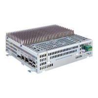
Describes the information found on the product's nameplate, including model number, ratings, and certifications.
Presents block diagrams illustrating the system architecture and operational concept of the drive system.
Lists detailed technical specifications, ratings, and parameters for the axis module.
Covers environmental requirements, ventilation strategies, and mounting guidelines for optimal operation.
Specifies requirements and considerations for the auxiliary power supply for the system.
Key instructions and precautions to be followed before and during the installation process.
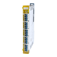
Specific guidelines for correctly implementing and wiring the safety functions of the servo drive.
Guidance on planning the switchgear cabinet layout, including connection diagrams and pin assignments.
Details the internal switching circuit and block diagram for implementing safety functions.
Explains how safety functions are controlled via digital inputs and the expected system status.
Outlines the procedure and conditions for testing the safety function's correct operation.
Provides a wiring example for integrating conventional switch contacts into the safety function.
Illustrates how to connect the safety functions using a safety PLC with error-proof outputs.
Discusses the requirements for personnel-safe control of the holding brake, including additional safety contacts.
Details the standard configuration and wiring for the motor connectors (X11, X21).
Describes the classic emergency stop function (stop category 0) for motor control, including component calculations.
Lists the types of feedback devices supported by the servo drive via connectors X12 and X22.
Explains the setup and connection for resolver feedback systems, including cable length limits.
Details the EnDat® encoder interface, cable length, and calculation for maximum cable length.
Describes the Hiperface® encoder interface, its high-resolution capabilities, and cable length limits.
Covers Sine Encoder feedback systems, their application, and maximum cable length.
Explains how to connect Sanyo Denki motors with absolute encoders to the MDD 100.
Details the Panasonic feedback analysis and supported encoder types.
Describes the BiSS C feedback analysis and its supported features.
Provides instructions and a checklist for replacing components of the servo drive system.
Guidelines for safe transport, proper storage, and environmentally sound disposal of the servo drive.
Information on detecting and resolving faults and warnings using LED indicators and status registers.
Explains the status indications provided by the LEDs on each axis module for troubleshooting.
Lists common drive malfunctions, their causes, and recommended remedies for troubleshooting.
Details the status register bits, fault codes, causes, and remedies for drive errors.
Guidelines for correctly wiring VARAN components between control cabinets and external nodes, including shielding.
Recommendations for wiring VARAN bus cables outside the control cabinet, emphasizing IP67 components.
Best practices for shielding VARAN bus lines within the control cabinet to prevent electromagnetic interference.
Advice on shielding power components that generate strong electromagnetic noise to ensure system integrity.
Recommendations for shielding VARAN bus connections between two separate control cabinets.
| Brand | SIGMATEK |
|---|---|
| Model | MDD 121-1 |
| Category | Control Unit |
| Language | English |