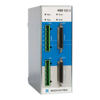
MDD 121-1
10.03.2021 Page 31
3.3.4 Connector properties
All connections of the servo drive system (except the ground bolt) are plugging style
connectors. This makes it easier to install the cables and to replace a drive. Never the less
it also opens the possibility to create cable sets for high volume machines.
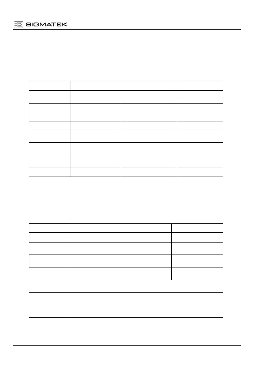
The mechanical properties of the interface connectors are:
0.2 – 1.5 mm² (16 – 24
AWG)
Phoenix
GMSTB2,5HCV/9-ST-
7,62
1 – 2.5 mm² (14 – 16
AWG)
0,56-0,79 Nm
(5-7 inch lb)
0.2 – 1.5 mm² (16 – 24
AWG)
D-Sub 25 with metal
housing
0.25 – 0.5 mm² (20-22
AWG)
1 – 2.5 mm² (14 – 16
AWG)
0,56-0,79 Nm
(5-7 inch lb)
3.3.5 Wire sizing
According to EN 60204 (for AWG: table 310-16 of the NEC 60 °C or 75 °C column), we
recommend
1.0 mm² (16 AWG), shielded, max.25 m,
capacitance <150 pF/m
Min. 0.5 mm² (18 AWG), part of the motor cable,
shielded separately, check voltage drop
Resolver with
thermal contact
4x2x0.25 mm² (22 AWG), twisted pairs, shielded, max.25 m, capacitance
<120 pF/m
7x2x0.25 mm² (22 AWG) twisted pairs, shielded, max.10 m, capacitance
<120 pF/m
Maximum 2.5 mm² (14 AWG), check voltage drop
Note: Use 60/75 °C Copper conductors only!
 Loading...