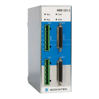
MDD 121-1
10.03.2021 Page 23
• Route the motor and control cables separately (distance about
100 mm). This improves the noise level of the control signals because
of the high radiation of the motor cables. Use only screened motor
and feedback cable with shield connections on both ends.
• The prescribed mounting position is vertical as shown on page 29.
• The airflow in the switchgear cabinet has to be in a way, that the servo
drives has enough cool and filtered air. See Ambient conditions
page 19.
• Any modification of the servo drive will invalidate the warranty,
except setting the software functions by parameter.
• At start-up of the servo drive, check the setting of the peak current of
the servo drive. Especially small motors are damaged very quickly, if
the setting of the servo drive is too high (e.g. a 1 A – motor and the
6 A-unit, not reduced to 1 A!)
3.2 Important instructions for the Safety Function
• All control components (switches, relays, PLC, etc.) and the control
cabinet must comply with the requirements of the ISO 13849. This
includes:
– Door – switches, etc. with protection class IP54 as minimum
– Control cabinet with protection class IP54 as minimum
• Use adequate insulated wire end sleeves
• External source voltage at the inputs ENABLE_L and ENABLE_H has
to be excluded in the cabinet and outside. Make sure, that short
circuits between single cables are excluded! See also EN ISO 13849.
• All safety-relevant cables (e. g. control cable) has to be installed e. g.
in a cable duct, if pass outside the control cabinet
• The connector pin X1 / 3 is marked as “reserved” and must not be
connected externally
• If the safety function SS1 (Safe Stop 1) is used, the minimum switch-
off time is 0.4 s. Following actions which need the safety function STO
(Safe Torque off) e.g. manually engagement into the machine, must
not be released before 1 s
 Loading...