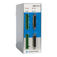
MDD 121-1
Page 2 10.03.2021
1 Overview ..................................................................................... 1
1.1 Components of a servo system ................................................... 4
2 General ....................................................................................... 5
2.1 About this manual ....................................................................... 5
2.2 Symbols used in this manual....................................................... 6
2.3 Safety Instructions ...................................................................... 7
2.4 Conformity with European Directives ........................................ 10
2.5 Prescribed use .......................................................................... 11
2.6 Non-prescribed use ................................................................... 12
2.7 Nameplate ................................................................................ 13
2.8 Block Diagram and Concept...................................................... 14
2.9 Technical Data Axis Module 400 V/480 V ................................. 19
2.10 Ambient conditions, ventilation and mounting ........................... 21
2.11 Auxiliary Power Supply ............................................................. 21
3 Installation ................................................................................ 22
3.1 Important instructions ................................................................ 22
3.2 Important instructions for the Safety Function ........................... 23
3.3 Planning of the switchgear cabinet ............................................ 25
3.3.1 Connection diagram and pin assignment of the axis module ................ 25
3.3.2 Ground .................................................................................................. 27
3.3.3 Mechanical construction and mounting ................................................. 29
3.3.4 Connector properties ............................................................................. 31
3.3.5 Wire sizing ............................................................................................. 31
3.3.6 External Fusing ..................................................................................... 32
3.3.7 Usage of cooling units ........................................................................... 33
3.3.8 Turn on/off response of the servo amplifier ........................................... 35
3.3.9 Holding brake control ............................................................................ 36
4 Safety Function ........................................................................ 37
4.1 Implementation ......................................................................... 38
4.1.1 Block IN ................................................................................................. 38
4.1.2 Blocks AMV, OPTO 01 and OPTO 02 ................................................... 39
4.1.3 Blocks CONTR 01, CONTR 02, AMP 01, AMP 02 and TR ................... 39
4.1.4 Blocks G01 and REL01 ......................................................................... 39
4.2 Function .................................................................................... 40
4.3 Function Test ............................................................................ 42
4.3.1 Test conditions ...................................................................................... 42
4.4 Example Connection with Switching Contacts ........................... 43
4.5 Example: Safety PLC Application .............................................. 44
5 Interfaces .................................................................................. 46
5.1 Motor connector (X11, X21) ...................................................... 46
5.1.1 Standard configuration .......................................................................... 46
4.4.2 Classic emergency stop function (stop category 0) ............................... 47