EasyManuals Logo

SIGMATEK MDD 121-1 User Manual

SIGMATEK MDD 121-1
74 pages
To Next Page IconTo Next Page
To Previous Page IconTo Previous Page
Page #38 background imageLoading...
Page #38 background image
MDD 121-1
Page 38 10.03.2021
4.1 Implementation
The following block diagram gives an overview of the internal switching circuit.
Motor
Main Power
Supply
0.5s
µP
ENABLE_H
ENABLE_L
Mains potential
UU
VV
WW
Astable Multi-
vibrator
IN AMV
Digital I/O potential
OPTO 01
OPTO 03
Electronic potential
TR
AMP 01
U_Treiber
CONTR 01
CONTR 02
Super
visor
1
Super
visor
2
S1
S2
REL 01
G 01
Control
OPTO 02
AMP 02
U_Treiber
U_Treiber
U_Treiber
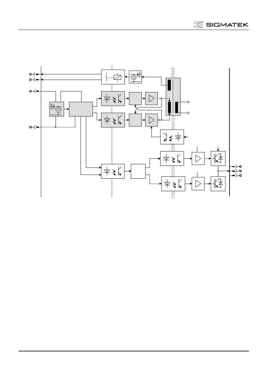
Block diagram for safe restart lock
The blocks in the diagram above have the following functions:
4.1.1 Block IN
The input block IN generates the supply voltage for the AMV block. This is formed from the
voltage difference between ENABLE_H and ENABLE_L. Power is therefore available
shortly after the appropriated signal is applied to ENABLE_H and ENABLE_L. The voltage
difference between ENABLE_H and ENABLE_L must exceed the minimum HIGH signal.
The LOW signal ranges from 0 V to +5 V.
The High signal ranges from +15 V to +30 V.
If the input voltage is disconnected, the block maintains the supply voltage for the AMV
block for approximately 400 ms. Because the differential voltage is supplied to the OPTO03
block without a delay, the motor can be actively slowed before the amplifier goes into the
safe status by disabling U_Treiber.
S3
S4

Table of Contents

Questions and Answers:

Question and Answer IconNeed help?

Do you have a question about the SIGMATEK MDD 121-1 and is the answer not in the manual?

SIGMATEK MDD 121-1 Specifications

General IconGeneral
BrandSIGMATEK
ModelMDD 121-1
CategoryControl Unit
LanguageEnglish

Related product manuals