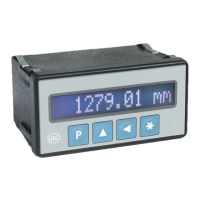
MA10/4-S
Date: 21.02.2019 Page 25 of 28 Art.No. 87181 Mod. status 50/19
10 MA10/4 in combination with MSK magnetic sensor
The parameters of the following table are intended for displaying the
maximum resolution of the relevant sensor. Therefore, all sensor resolutions
that are unequal 0.1, 1, 10, 100 cause jumps in the lowest decimal position.
The resolution of the MA10/4 may be decreased by programming an
DIVISOR: = "10" if this is not desired. The DEC: decimal point must be
adjusted correspondingly.
If the MA10/4 is to be operated with an MSK type magnetic sensor, some parameters must be
fixed.
Parameter DIVISOR: = "1"
Parameter INDEX: = "0-kurz"
25 μm
50 μm
100 μm
125 μm
500 μm
10 μm
10 μm
100 μm
100 μm
100 μm
0.04 mm
0.05 mm
0.08 mm
0.1 mm
0.16 mm
0.2 mm
0.8 mm
0.01 mm
0.01 mm
0.01 mm
0.1 mm
0.1 mm
0.1 mm
0.1 mm
0.00
0.00
0.00
0.0
0.0
0.0
0.0
5 μm
10 μm
12.5 μm
20 μm
25 μm
50 μm
1 μm
10 μm
10 μm
10 μm
10 μm
10 μm
0.000
0.00
0.00
0.00
0.00
0.00
MA10/4 combined with an MSK magnetic sensor and the MR magnetic ring
If an MSK magnetic sensor with an MR magnetic ring is used instead of an incremental
encoder, then the "encoder pulses per revolution" of the magnetic ring must be determined in
order to enable parameterization of the magnetic display. The "encoder pulses per revolution" is
calculated from the pose number of the magnetic ring and the scaling factor of the MSK sensor
according ro the following formula:
Encoder pulses per revolution = number of poles of magnetic ring x scaling factor of sensor

 Loading...