10
ENG
FR
insulated with a glass wool pipe insula-
tor 30 mm (1 in) thick, with a density of
50 kg/m
3
(3lb/ft
3
) or follow vent
manufacturers instructions for clearan-
ces to combustibles.
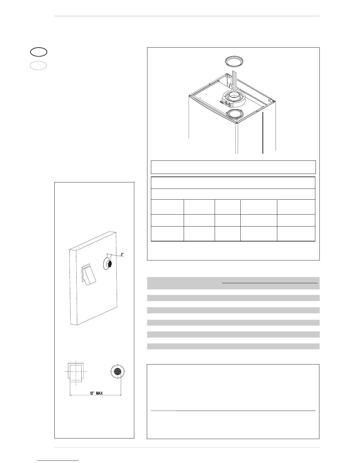
4. The distance between the intake air and
the smoke pipe must be within 300 mm
(12 in) - (see fig. below).
5. The head loss of the smoke pipe cannot
exceed by more than 4.8 mm (0.19 in)
of the intake head loss.
6. Outlet terminal must be flush with the
wall and the inlet terminal must protru-
de at least 50 mm (2 in) from the out-
stide wall (see fig. below).
The maximum overall length of the intake
and exhaust ducts depends on the head
losses of the single fittings installed and
must not be greater than 12 mm H
2
O
(0.472 “W.C.).
With outlet type C12, install diaphragm ø 86 mm/3.4 inch only if the coaxial flue is
less than 1 metres (3.3 feet) long.
With outlet type C32, use the following diaphragms, depending on flue length and without
any additional curves:
Installations with vertical Installations with vertical condensation
extension L. 200 mm/7.9 inch code 8086908 collector code 8092803
Diaphragm Diaphragm Without Diaphragm None
ø 86/3.4”
ø 87.5/3.44”
diaphragm
ø 87.5/3.44
” diaphragm
(cod. 6028623) (cod. 6028624) (cod. 6028624)
L min = 1,3 m L min = 2,5 m L min = 4 m L min = 2,5 m
4.27 ft 8.2 ft 13.1 ft 8.2 ft
L max = 2,5 m L max = 4 m L max = 5 m L max = 2,5 m L max = 4 m
8.2 ft 13.1 ft 16.4 ft 8.2 ft 13.1 ft
Figure 6/a
Example of allowable installation calculation in that the sum of the head losses of the single fit-
tings is less than 7.0 mm H
2
O (0.276 “W.C.H
2
O):
Intake Outlet
23ft horizontal pipe ø 3” mm x 0.30 2,1 --–--
23ft horizontal pipe ø 3” x 0.13 --–-- 0,91
n° 2 90° elbows ø 3” x 0.65 1,3 --–--
n° 2 elbows 90° ø 3” x 0.50 --–-- 1,0
n° 1 terminal ø 3” 0,2 2,0
Total head loss 3,6 + 3,91 = 7,51 mmH2O
(
0.296 “W.C.
H
2
O
)
With this total head loss, remove the segments from n. 1 to n. 9
from diaphragm in the intake pipe.
TABLE 1
Vent Accessories ø 3”
Load loss in mm H
2
O (“W.C.H
2
O)
Intake Outlet Roof outlet/Intakes
45° curve MF 0.6 (0.024) 0.3 (0.012) -------
90° curve MF 0.65 (0.026) 0.5 (0.020) -------
Extension L. 1000 mm/39.4 inch (horizontal) 0.3 (0.012) 0.13 (0.005) -------
Extension L. 1000 mm/39.4 inch (vertical) 0.3 (0.012) 0.06 (0.002) -------
Terminal 1 (Termination box : 2SVSRTF) ------- 0.8 (0.0315) -------
Terminal 2 (Termination hood : 2SVSHTX) ------- 0.6 (0.0236) -------
Intake terminal 0.2 (0.008) ------- -------
Manifold 0.3 (0.012) ------- -------
Roof outlet terminal L.1390 ------- ------- 0.6 (0.024)
Condensation collection T ------- 1.1 (0.043) -------
Figure 7
Slanted view
Frontal view