11
ENG
FR
(A
TTENTION! The total length of linear
exhaust sections should not exceed 8 m
(26 ft) as compared to the total length of
linear suction sections
).
For head losses in the fittings, refer to Table
1 and example fig. 7.
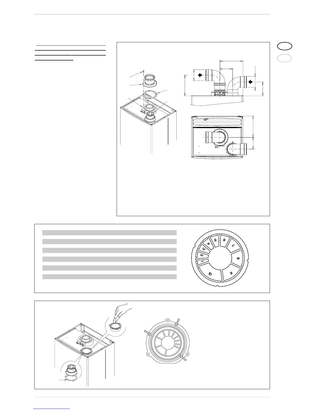
2.7.1 Separate flue kit (fig. 8)
The separate flue kit code 8089909 is
supplied with an intake diaphragm which
must be used as shown in fig. 8/a, depen-
ding on the maximum load loss permitted
in both flues. To use the air intake in this
type of outlet you must perform the fol-
lowing operations (fig. 9):
1 Remove the base of the air intake, using
a tool to cut it off (a);
2 Overturn the air intake (b) and replace
the seal (5) with the seal supplied in the
kit code 8089909;
3 Insert the intake diaphragm supplied in
the kit code 8089909, pushing it in until
it is in contact with the bottom bead.
You can now insert the extension or curve
in its housing to complete the intake. You
need not use any seal or sealant, as gasket
provided is sufficient.
2.7.2 Outlet systems
The diagrams in fig. 9/a illustrate a num-
ber of examples of different types of sepa-
rate outlets.
Figure 9
Figure 8/a
N° segments to remove Load loss (mm H
2
O) (“W.C.H
2
O)
n° 1 and 2 0 - 1.0 0 - 0.039
from n° 1 to 3 1.0 - 2.0 0.039 - 0.079
from n° 1 to 4 2.0 - 3.0 0.079 - 0.12
from n° 1 to 5 3.0 - 4.0 0.12 - 0.16
from n° 1 to 6 4.0 - 5.0 0.16 - 0.20
from n° 1 to 7 5.0 - 6.0 0.20 - 0.24
from n° 1 to 8 6.0 - 7.0 0.24 - 0.28
from n° 1 to 9 7.0 - 8.0 0.28 - 0.31
from n° 1 to 10 8.0 - 10.0 0.31 - 0.39
without diaphram 10.0 - 12.0 0.39 - 0.47
IMPORTANT: The three housings
on the diaphragm permit assem-
bly of the air intake in one posi-
tion only.