2.5 SYSTEM FILLING
Filling of the boiler and the system is done
by the charge cock (2 fig. 6).
The charge pressure, with the system cold,
must be between 1 and 1.2 bar.
During system filling you are recommended
to keep the main switch turned OFF.
Filling must be done slowly so as to allow
any air bubbles to be bled off through the
air valves.
Should the pressure have risen well
above the limit expected, discharge the
over pressure by opening the pressure-
relief valve.
2.6 FLUE
The flue for the atmospherical expulsion of
the combustion products from natural
draught appliances must meet the following
requirements:
–
Be gas-tight to the combustion products,
waterproof and thermally insulated.
–
Be built of materials suitable for keep
resisting to normal mechanical stresses,
heat, and the action of combustion pro-
ducts and their possible condensates.
– Follow a vertical path and not present
any throttling throughout its entire
length.
– Be adequately insulated to prevent phe-
nomena of condensation or smokes coo-
ling, in particular if located outside the
building or in unheated ambiences.
– Be set at an adequate distance from
combustible or easily inflammable mate-
rial by means of an air gap or suitable
insulating material.
– Have beneath the mouth of the first
smoke duct a chamber for collecting
solid material and any condensate; the
height of the chamber must be at least
500 mm.
Access to the chamber must be guaran-
teed by means of an opening provided
with an air-tight metal door.
– Have a circular, square, or rectangular
internal cross section; in the case of
square or rectangular sections, the cor-
ners must be rounded off with a radius
of not less than 20 mm. However,
hydraulically equivalent cross sections
are allowed.
– Be equipped with a chimney-pot at the
top, which must be outside the so-called
back-flow zone, so as to prevent the for-
mation of back-flow, which prevents free
discharge of the products of combustion
into the atmosphere.
– Be devoid of mechanical means of suc-
tion located at the top of the pipe.
– No overpressure should be present in a
chimney that passes within or close up
to inhabited rooms.
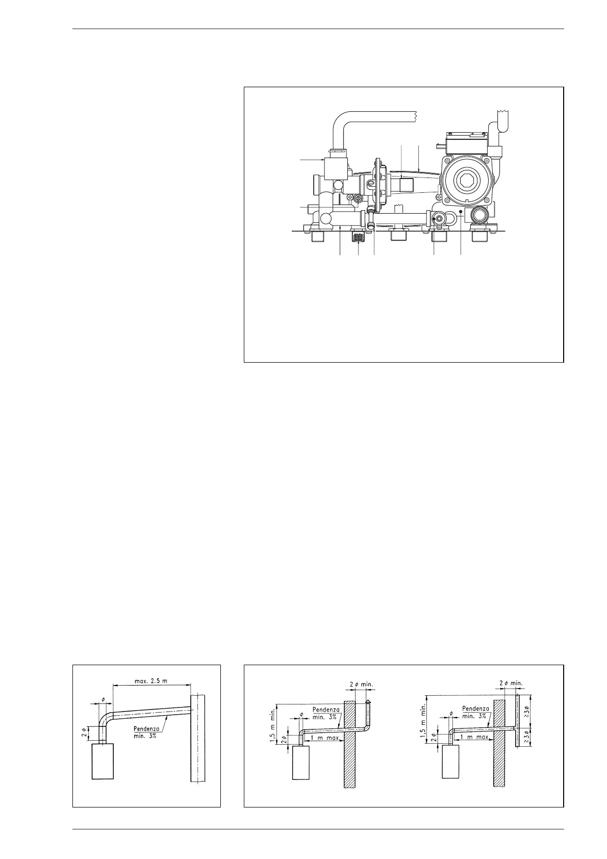
2.6.1 Connecting up flue
Fig. 6 refers to the connection of the boiler
“25 OF” to the flue or chimney through
smoke ducts. When making the connec-
tion, in addition to respecting the dimen-
sions given, you are recommended to use
gas-tight materials capable of resisting
over time mechanical stresses and the
smokes heat.
At any point along the smoke duct, the tem-
perature of the combustion products must
be higher than the dew point. More than a
total of three changes of direction must not
be made, including the inlet connection to
the chimney/flue.
For any changes of direction use only cur-
ved pipe lengths.
Fig. 6/a shows some applications of drau-
ght terminals that ensure proper expulsion
of the combustion products, in case of
discharge through the wall.
2.7 COAXIAL DUCT
The air inlet-smoke outlet assembly ø
60/100 is supplied in a kit code 8084805
complete with mounting instructions.
2.7.1 Coaxial duct accessories
The accessories to be used for this type of
installation and some of the connecting
systems that may be adopted are illustra-
ted in fig. 7.
74
 Loading...