4.1 TEMPERATURE
ADJUSTMENT OF D.H.W.
The sistem with a potentiometer for adju-
sting the temperature of D.H.W. with a set-
ting range from 30° to 60°C offers a dou-
ble advantage:
1) The boiler adapts perfectly to any type of
D.H.W. system, whether the mixing
system is a mechanical or a thermostat-
controlled type.
2) The thermal output is dosed according
to the temperature required, which
means a considerable saving in fuel.
NOTE: In order to avoid any misunder-
standing please remember that the value
obtained by the product of temperature
difference (in °C) between D.H.W. output
and input into the boiler by the hourly
flow rate measured on the tap, where
hot water is drawn off (l/h), cannot be
higher than the useful output developed
by the boiler. For measurements and
checks on flow rate and temperature of
D.H.W., use suitable instruments, taking
into consideration any heat dispersion
along the stretch of piping between the
boiler and the measuring point.
4.2 ADJUSTMENT OF
D.H.W. FLOW RATE
To adjust the D.H.W. flow rate, use the flow
rate adjuster (5 fig. 6).
Remember that the flow rates and corre-
sponding temperatures of use of hot water,
given in section 1.3, have been obtained by
positioning the selector of the circulation
pump on the maximum value.
Should there be any reduction in the
D.H.W. flow rate, the filter installed on the
inlet to the divertor valve (3 fig. 6) will
need cleaning.
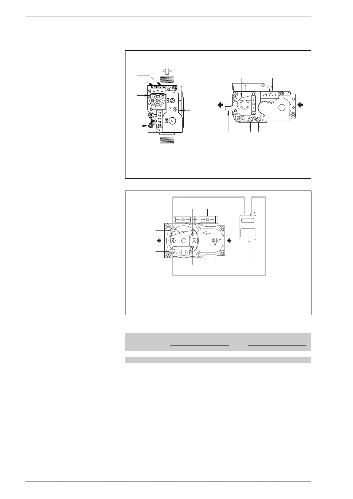
4.3 GAS VALVE
The boilers are equipped standard with the
SIT 845 SIMGA/HONEYWELL VK 4105M
gas valve (fig. 23) and WHITE-RODGERS
91B05S. gas valve (fig. 24).
The gas valve is set at two pressure values:
maximum and minimum.
According to the type of gas burnt, these
correspond to the values given in Table 4.
The gas pressures at the maximum and
minimum values, are factory set. Conse-
quently they must not be altered.
Only when you switch the appliance from
one type of gas supply (methane) to
another (butane or propane), it is permit-
ted to alter the operating pressure.
It is essential that this operation is carried
out exclusively by authorized technical
staff. When the working pressures have
been adjusted, reseal the regulators.
When the gas pressures are to be reset,
this must be done following a set order
depending on the type of valve:
– First the MAXIMUM and then the MINI-
MUM for the SIT 845 SIGMA and
HONEYWELL VK 4105M
gas valve.
–
First the MINIMUM and then the MAXI-
MUM for the WHITE-RODGERS
91B05S gas valves.
4.3.1 Maximum and minimum
pressure adjustment
SIT 845 SIGMA
To set the maximum pressure, proceed as
follows (fig. 25):
–
Connect the pressure column to the pres-
sure inlet downstream of the gas valve.
– Remove the plastic cap (1).
– Set the knob of the D.H.W. potentiome-
ter to the maximum value.
–
Ignite the boiler and open the hot
water cock.
–
Using a ø 10 spanner, turn the nut (3)
to arrive at the maximum pressure
value given in Table 4: to reduce the
pressure, turn the nut counterclockwi-
se; to increase the pressure, turn it
clockwise.
–
Operate the main switch a number of
times, keeping the hot water tap open
all the time, and check that the pressu-
re corresponds to the values given in
Table 4.
83
4 USE AND MAINTENANCE
TABLE 4
Burner max. Modulator Burner min. Modulator
Type of gas pressure current pressure current
mbar mA mbar mA
Methane (G20) 9,5 130 1,4 0
Butane (G30) 27,7 165 5,1 0
Propane (G31) 35,3 165 6,1 0
 Loading...