The boiler must be installed in a fixed loca-
tion and only by specialized and qualified
firms in compliance with all instructions
contained in this manual.
Furthermore, the installation must be in
accordance with current standards and
regulations.
2.1 VENTILATION OF
BOILER ROOM
The “25 OF”
version boilers must be instal-
led in adequately ventilated domestic
rooms. It is essential that in rooms where
the boiler are installed at least as much air
can arrive as required by normal combu-
stion of the gas consumed by the various
appliances. Consequently, it is necessary to
make openings in the walls for the air inlet
into the rooms.
These openings must meet the following
requirements:
– have a total free section of at least 6
cm
2
for every kW of heat input, with a
minimum of 100 cm
2
;
– They must be located as close as possi-
ble to floor level, not prone to obstruc-
tion and protected by a grid which does
not reduce the effective section required
for the passage of air.
The “25 BF” version boilers may instead be
installed, without any constraints regarding
location or supply of air for combustion, in
any domestic rooms.
2.2 INSTALLATION PLATE
The optional installation plate code
8075407 is supplied with an instruction
sheet for the fixing.
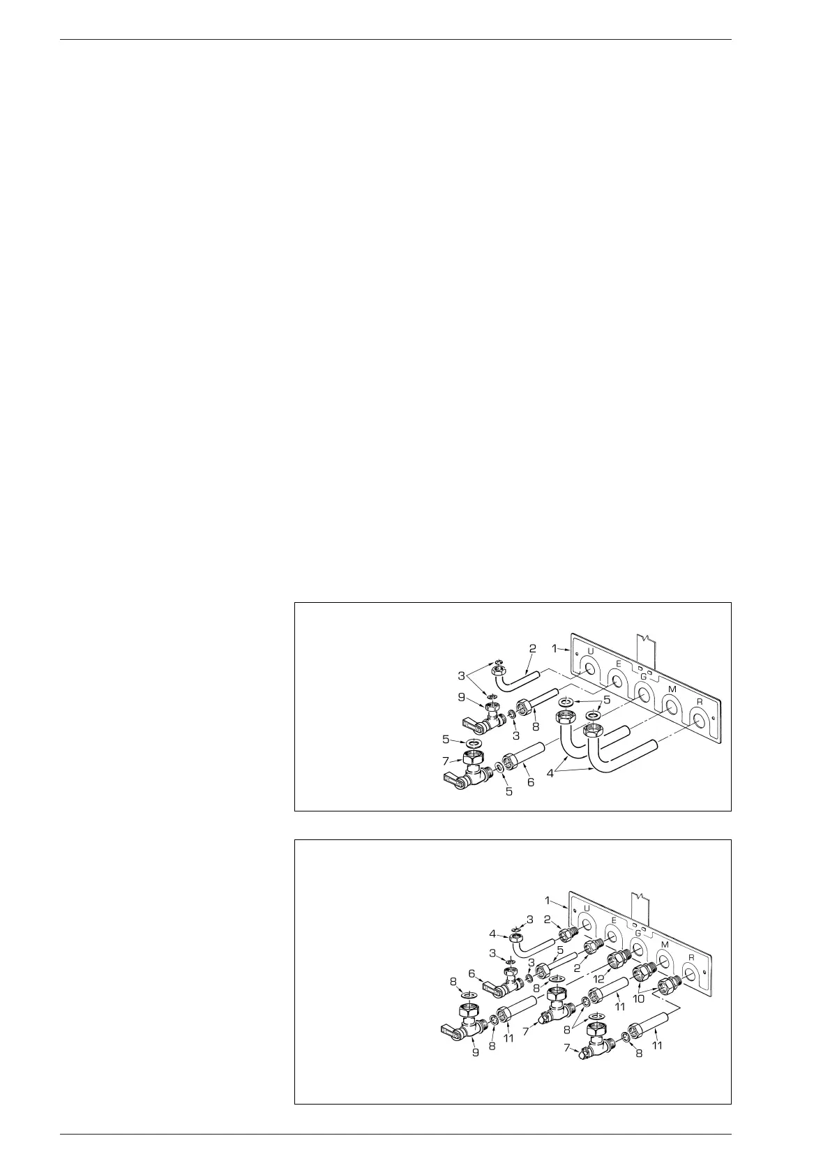
2.2.1 Fitting the pipe
elbows (optional)
To fit the connecting elbows supplied in kit
code 8075418, follow the instructions
reported in fig. 4.
2.2.2 Fitting isolating
valves (optional)
To fit the isolating valves, supplied in kit code
8091806, follow the instructions mentio-
ned in fig. 4/a.
2.2.3 Replacement wall kit
for other makes (optional)
The kit code 8093900 is supplied comple-
te with mounting instructions.
2.3 CONNECTING UP SYSTEM
Before proceeding to connect up the boiler,
you are recommended to make the air cir-
culating in the piping in order to eliminate
any foreign bodies that might be detrimental
to the operating efficiency of the appliance.
When making the hydraulic connections,
make sure that the dimensions indicated in
fig. 1 are respected.
The discharge pipe of the safety valve
must be connected to a collector funnel
for channelling away any discharge if the
safety valve goes into action.
The gas connection must be made using
seamless steel pipe (Mannesmann type),
galvanized and with threaded joints provi-
ded with gaskets, excluding three-piece
connections, except for initial and end con-
nections.
Where the piping has to pass through
walls, a suitable insulating sleeve must be
provided.
When sizing gas piping, from the meter to
the boiler, take into account both the volume
flow rates (consumption) in m
3
/h and the
relative density of the gas in question.
The sections of the piping making up the
system must be such as to guarantee a
supply of gas sufficient to cover the maxi-
mum demand, limiting pressure loss
between the gas meter and any apparatus
being used to not greater than:
– 1.0 mbar for family II gases (natural gas);
– 2.0 mbar for family III gases (butane or
propane).
An adhesive data plate is sticked inside the
front panel; it contains all the technical data
identifying the boiler and the type of gas for
which the boiler is arranged.
2.3.1 Filter on the gas pipe
The gas valve is supplied ex factory with an
inlet filter, which, however, is not adequate
to entrap all the impurities in the gas or in
gas main pipes.
To prevent malfunctioning of the valve, or in
certain cases even to cut out the safety
device with which the valve is equipped,
install an adequate filter on the gas pipe.
2.4 CHARACTERISTICS
OF FEEDWATER
It is absolutely essential that the water for
the central heating system is to be treated
in the following cases:
– very extensive system (with high con-
tents of feedwater);
– frequent addition of makeup water into
the system;
– should it be necessary to empty the
system either partially or totally.
73
2 INSTALLATION
KEY
1 Fixing jig
2 Elbow 1/2”x14
3 Gasket ø 18.5/11.5
4 Elbow 3/4” x 18
5 Gasket ø 24/17
6 Copper pipe 3/4”x18
7 Gas cock 3/4” MF
8 Hot water tap section
9 D.H.W. inlet tap 1/2”
Fig. 4
Fig. 4/a
KEY
1 Fixing jig
2 Straight coupling 1/2”x14
3 Gasket ø 18.5/11.5
4 Elbow 1/2”x14
5 Copper pipe 1/2”x14
6 Isolation valve 1/2” MF
7 Isolation valve 3/4” MF
8 Gasket ø 24/17
9 Gas cock 3/4” MF
10 Straight coupling
3/4”x18
11 Copper pipe 3/4”x18
12 Straight coupling
3/4”x18 with olive
 Loading...