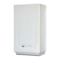
code 8092203. To fit the timer, remove
the housing blanking piece from the control
panel and, with the panel open, fit the timer
to the panel using the screws supplied the-
rein. Remove the faston that links the ter-
minal 3 of the rotary switch and connect it
to the terminal 3 of the time-clock.
Connect the unit as shown in the wiring
diagram (fig. 21).
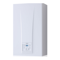
3.9 MAINS ELECTRICITY
CONNECTION
Use a separate electric line to link up the
room stats and relative zone valves.
The micro or relay contact connection is
made to terminals 10-11 of the “TA” con-
nector of circuit board after having remo-
ved the jumper (fig. 22).
82