Electrical 9
WIRING CONNECTIONS
Fire hazard. Incorrect voltage can cause a
fire or seriously damage the motor and voids the warran-
ty. The supply voltage must be within ±10% of the motor
nameplate voltage.
NOTICE: Dual-voltage motors are factory wired for 230
volts. If necessary, reconnect the motor for 115 volts, as
shown. Do not alter the wiring in single voltage motors.
Install, ground, wire, and maintain your pump in compli-
ance with the National Electrical Code (NEC) or the
Canadian Electrical Code (CEC), as applicable, and with
all local codes and ordinances that apply. Consult your
local building inspector for code information.
Connection Procedure:
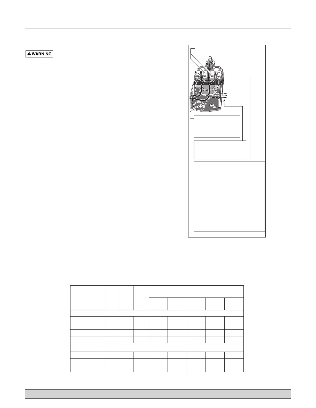
1. Connect the ground wire first as shown in Figure 13.
The ground wire must be a solid copper wire at least
as large as the power supply wires.
2. There must be a solid metal connection between the
pressure switch and the motor for motor grounding
protection. If the pressure switch is not connected to
the motor, connect the green ground screw in the
switch to the green ground screw under the motor
end cover. Use a solid copper wire at least as large as
the power supply wires.
3. Connect the ground wire to a grounded lead in a ser-
vice panel, to a metal underground water pipe, to a
metal well casing at least ten feet (3M) long, or to a
ground electrode provided by the power company or
the hydro authority.
4. Connect the power supply wires to the pressure
switch as shown in Figure 13.
For parts or assistance, call Simer Customer Service at 1-800-468-7867 / 1-800-546-7867
Figure 13: Pressure Switch
on the terminal screws.
green ground screw.
the white (neutral) wire. It
goes to which screw.
one). Connect the white
(neutral) wire to the other screw.
red wires.
Wiring Chart – Recommended Wire and Fuse Sizes
Branch Distance in Feet (Meters);
Max Fuse Wire Size AWG (mm
2
)
Load Rating 0-100 101-200 201-300 301-400 401-500
Model HP Amps Amps (0-30) (31-61) (62-91) (92-122) (123-152)
115 Volts:
2805E-01 1/2 9.9 15 14(2) 12(3) 10(5.5) 8(8.4) 8(8.4)
2806E-01 1/2 9.9 20 12(3) 10(5.5) 8(8.4) 6(14) 6(14)
2810E-01 3/4 12.4 20 12(3) 10(5.5) 8(8.4) 6(14) 6(14)
2815E-01 1 14.8 20 12(3) 8(8.4) 6(14) 6(14) 4(21)
230 Volts:
2806E-01 1/2 4.95 15 14(2) 14(2) 14(2) 12(3) 12(3)
2810E-01 3/4 6.2 15 14(2) 14(2) 14(2) 12(3) 12(3)
2815E-01 1 7.4 15 14(2) 14(2) 14(2) 12(3) 10(5.5)