Installation 6
For parts or assistance, call Simer Customer Service at 1-800-468-7867 / 1-800-546-7867
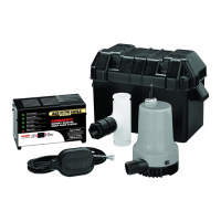
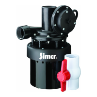
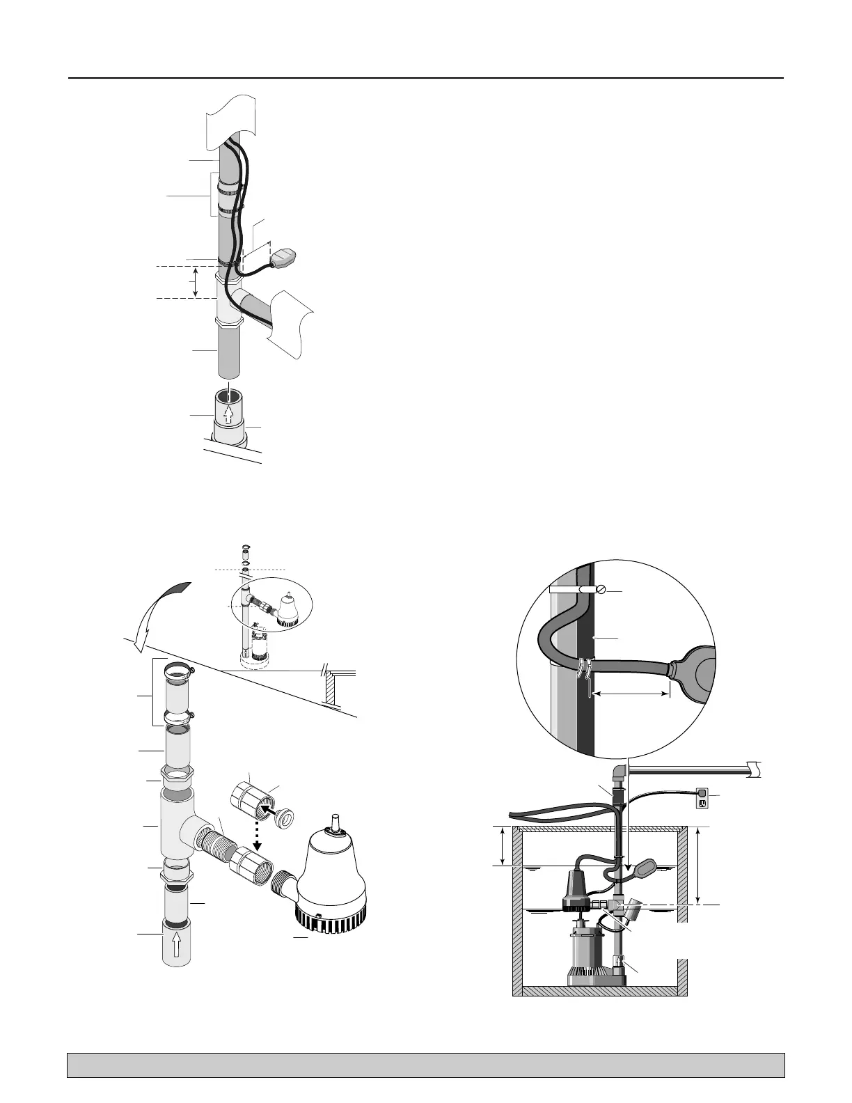
14. Mount the float switch assembly (Key No. 8) loosely
to the discharge pipe with the cable ties (Key Nos.
8A & 8B). See Figure 4. Approximately 2.5” (63.5
mm) of cord length should be left between the float
and the clamp. Do not tighten the cable ties.
Adjustments may be needed later.
15. Skip to the section “Installation of Double Pump
Assembly”, Page 7.
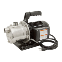
Method B
1. Make a second cut in the discharge pipe at the pen-
cil mark made in step 1 and set the cut-off piece of
discharge pipe aside. See Figure 5.
2. Wrap the threads of the close nipple (Key No. 3)
counterclockwise with 2 turns of teflon tape and set
aside.
NOTICE: There must be a check valve installed in
the Primary Sump Pump discharge between the tee
and the Primary Sump Pump. This will prevent recir-
culation into the Primary Pump when the Back Up
Sump Pump comes on. See Figure 5.
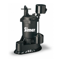
3. The backup pump (Key No. 5) and check valve
assembly (Key No. 4) come preassembled. Thread
the close pipe nipple into the check valve and pump
assembly.
4. Thread the close nipple into the tee (Key No. 2).
pipe.
may vary).
Figure 4 - Back-up pump float switch tether length and
discharge pipe
Figure 5 – Method B – Make the second cut for installa-
tion of the backup pump and check valve assembly.
Install the backup pump. Your installation may not
require the reducer bushings.
discharge pipe.
12" Min.
7" Min.