3-5
1. Using the 2120 Job Configuration Report, find the entry for the sensor base (4098-9792 and
4098-9789 only) you are about to install. The CUSTOM LABEL column provides the
location while the DEVICE ADDRESS column provides the switch setting data.
2. Using the switch setting data for the base you are installing, set the base’s address.
See Figure 3-1 for location of switches. Use a small screwdriver or pen to set the switches.
3. Double-check the location of the sensor base and its address before proceeding to electrical
installation (see Figure 2-1).
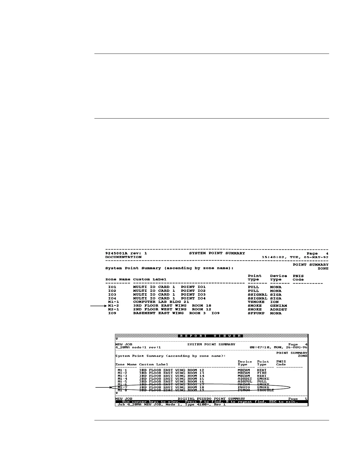
1. Using the Programmer’s Report for the 4020 (Figure 3-3), 4100+, 4100U, 4100ES, 4120,
4008, or 4010 (Figure 3-4), find the entry for the sensor base you are about to install. The
device ADDRESS and CUSTOM LABEL are located in the SYSTEM POINT SUMMARY
under “M.”For example, Address M1-7 (for the 4100+, 4100U, 4100ES, 4120, 4008, or 4010
system) is circled in Figure 3-4. M1 is the addressable channel while -7 is the device address
on the channel. For a base with Address M1-7, Address 7 must be set on the base’s DIP
Switches (SW1).
2. Using the example given in Step 1 as guideline, set the base’s address using the information in
Figure 3-5. See Figure 3-1 and 3-2 for location of DIP Switches. Use a small screwdriver or
pen to set the switches.
3. Mark an address label with the appropriate address for your base by shading a label box for
each base DIP Switch in the ON position. Then apply the label to the base near the base’s
DIP Switch.
4. Double-check the location of the sensor base and its address before proceeding to electrical
installation.
Figure 3-3. 4020 Programmer’s Report
Figure 3-4. 4100+, 4100U, 4100ES, 4120, 4008, or 4010 Programmer’s Report
Continued on next page
4098 TrueAlarm Sensor Bases,
Continued
Address Setting for
the 2120 CDT
System
Address Setting for
the 4010, 4020,
4100+, 4100U,
4100ES, 4008, or
4120 System
Device
Address
Device
Address