5-5
The following test method is suitable for functional checks of sensor bases or QuickConnect
sensors during installation; however, testing with smoke must be performed to comply with NFPA
requirements.
For all sensor bases, position the 553-810 Magnet Tester ½” to ¾” counterclockwise from the
visible LED found on the sensor base, (see the figure below).
For the 4098-9757 QuickConnect2 photo sensor, position the 553-810 Magnet Tester as shown in
Figure 5-2.
Testing a sensor with a magnet reports a value of 255 for actual / peak (exception 4010 panel,
4100U panel and 4100ES panel). Clear the peak value after testing.
Note: For 4098-9795 and 4098-9796 Multi-Sensor Bases both photo and heat address
(even and odd) must alarm.
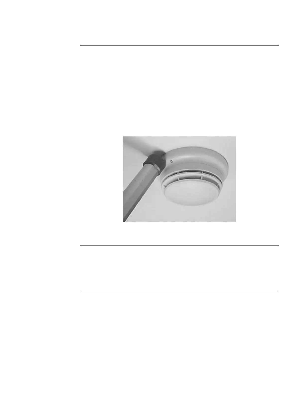
Figure 5-1. Magnet Test Location for 4098-9789, -9791, -9792, -9793, and -9796
Sensor Bases using 553-810 Magnet Tester
The 4098 photoelectric detectors may be tested by placing a magnet above the location indicated
by a “” mark embossed on the cover (see Figure 5-2) for four (4) seconds. Use the Magnetic
Tester (Part No. 553-810), Table 5-3, and the following information to test detectors.
Table 5-3 describes the LED reaction during Normal and MAG TEST modes to the Normal,
More Sensitive, Less Sensitive, and Non-Functional states of the detector.
Continued on next page
Maintenance and Testing,
Continued
Alternate Method for
Testing Sensors
Magnetic Test for
Photoelectric
Detectors