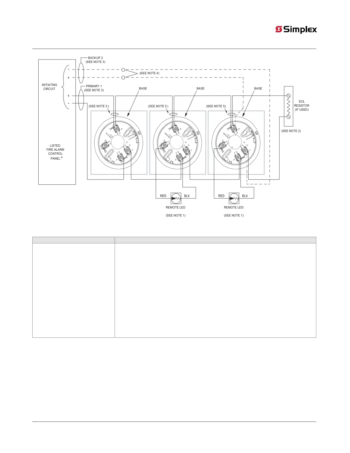
Figure 5: 4098-9788 Base connections for Style B or D initiating circuits
Table 5: Figure symbol reference
Symbol Reference
*
• 2120 Listed Fire Alarm Control Panel
• 4001 Listed Fire Alarm Control Panel
• 4002 Listed Fire Alarm Control Panel
• 4020 Listed Fire Alarm Control Panel
• 4100+ Listed Fire Alarm Control Panel
• 4100U Listed Fire Alarm Control Panel
• 4100ES Listed Fire Alarm Control Panel
• 4007ES Listed Fire Alarm Control Panel
• 4007ES hybrid Listed Fire Alarm Control Panel
• 4004 Listed Fire Alarm Control Panel
• 4005 Listed Fire Alarm Control Panel
• 4006 Listed Fire Alarm Control Panel
Note:
1. If used, the 4098-9830 Remote LED is polarized. Refer to Figure 8 to wire the remote LED to the heat detector. Observe color-
coded wiring.
2. Refer to the wiring diagrams provided with the system panel for the correct End-Of-Line (EOL) resistor value.
3. Wire the Primary-1 and the Backup-2 lines separate wire runs, and in compliance with local requirements.
4. For a Style D initiating circuit, wire according to the dotted lines and do not use EOL resistor.
5. Break the wires before connecting to Terminal 4 to maintain supervision. Do not loop the wire underneath Terminal 4.
page 15 574-709 Rev. AP
4098 Detectors, Sensors, and Bases Application Manual