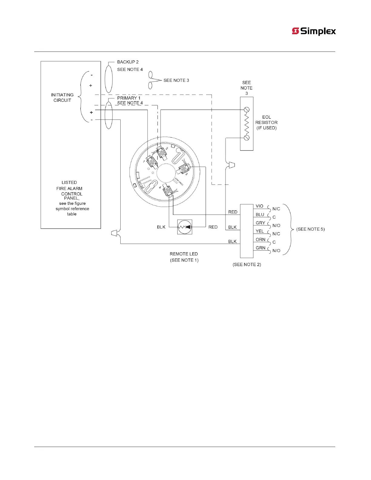
Figure 6: 4098-9683 2-Wire Relay Base connections for Style B or D initiating circuits
Note:
1. If used, the 4098-9830 remote LED is polarized. Refer to Figure 8 to wire the remote LED to a heat detector. Observe color-coded
wiring.
2. Only wire one relay base to an initiating circuit.
3. For a Style D initiating circuit, wire according to the dotted lines and do not use an EOL resistor. If it is a Style B initiating circuit,
refer to the wiring diagrams provided with the system panel for the correct EOL resistor value.
4. Wire the Primary-1 and the Backup-2 lines in separate wire runs, and in compliance with local requirements.
5. Aux. Relay contacts, each rated 1 A at 28 VDC / 0.5 A at 125 VAC, resistive.
page 16 574-709 Rev. AP
4098 Detectors, Sensors, and Bases Application Manual