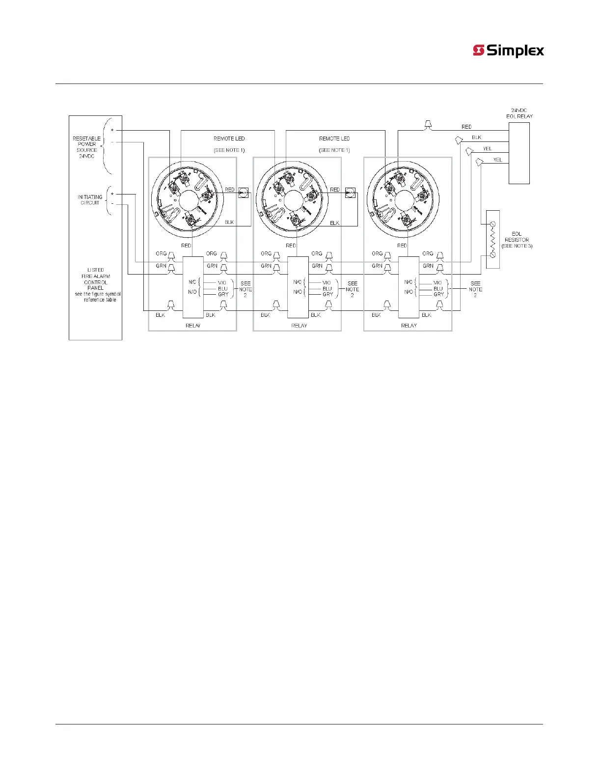
Figure 7: 4098-9682 4-Wire Base Connections for Style B Initiating
Circuits, featuring the 24VDC EOL Relay, 2098-9735 or 2098-9739
Note:
1. The figure shows the 4098-9830 remote LED. If used, the 4098-9830 remote LED is polarized. Observe color-coded wiring. Refer
to Figure 8 to wire the remote LED to the heat detector.
2. Aux. Alarm contacts - Form C - each rated 3 A at 28 VDC / 115 VAC, resistive.
3. Refer to the wiring diagrams provided with the system panel for the correct EOL resistor value.
page 17 574-709 Rev. AP
4098 Detectors, Sensors, and Bases Application Manual