EasyManuals Logo

Simplex 4100ES Installation Instructions

Simplex 4100ES
22 pages
To Next Page IconTo Next Page
To Previous Page IconTo Previous Page
Page #12 background imageLoading...
Page #12 background image
page 12 579-1015 Rev U
4100ES Extended Power Supply Installation Instructions
Add the alarm loads of all the devices on an SLC wire branch and apply to Equation 1.
Add the unit loads for all devices on an SLC wire branch and the number of isolators and apply to UTP Wiring Limit Based on Communication
in Figure 11.
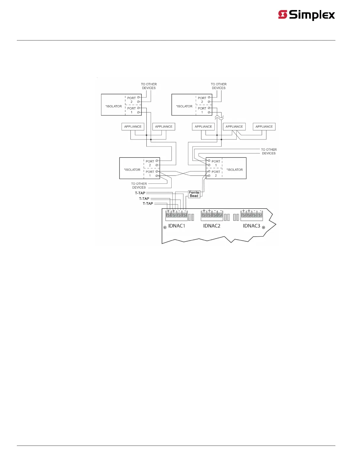
Maximum wire resistance protected by 1 isolator is 1.5 ohm (total, both wires).
Wire the devices as instructed in the Class B Wiring to Devices sections section.
Figure 15: Class B Wiring With Isolators
* 4905-9929 Isolator

Other manuals for Simplex 4100ES

Questions and Answers:

Question and Answer IconNeed help?

Do you have a question about the Simplex 4100ES and is the answer not in the manual?

Simplex 4100ES Specifications

General IconGeneral
TypeFire Alarm Control Panel
DisplayLCD
Battery BackupYes
Model4100ES
ManufacturerSimplex
Communication ProtocolOptional Ethernet
Signaling Line Circuits (SLCs)Up to 10
Notification Appliance Circuits (NACs)Up to 10
Agency ListingsUL, FM, CSFM, MEA
Max Relay Circuits20
Communication PortsEthernet
Operating Temperature32°F to 120°F (0°C to 49°C)
HumidityUp to 93% RH, non-condensing

Related product manuals