page 7 579-1015 Rev U
4100ES Extended Power Supply Installation Instructions
Wiring Overview
General Wiring Guidelines
• Conductors must test free of all grounds.
• All wiring must be done using copper conductors only, unless noted otherwise.
• If shielded wire is used:
- The metallic continuity of the shield must be maintained throughout the entire cable length.
- The entire length of the cable must have a resistance greater than 1 megohm to earthground.
• Underground wiring must be free of all water.
• In areas of high lightning activity, or in areas that have large power surges, the 2081-9027 Transient Suppressor should be used on monitor
points.
• Wires must not be run through elevator shafts.
• Splicing is permitted. All spliced connections must either be soldered (resin-core solder), crimped in metal sleeves, or encapsulated with an
epoxy resin. When soldering or crimped metal sleeves are used, the junction must be insulated with a high-grade electrical tape that is as
sound as the original insulating jacket. Shield continuity must be maintained throughout.
• A system ground must be provided for earth detection and lightning protection devices. This connection must comply with approved earth
detection per NFPA780.
• Only system wiring can be run together in the same conduit.
Power-Limited Guidelines
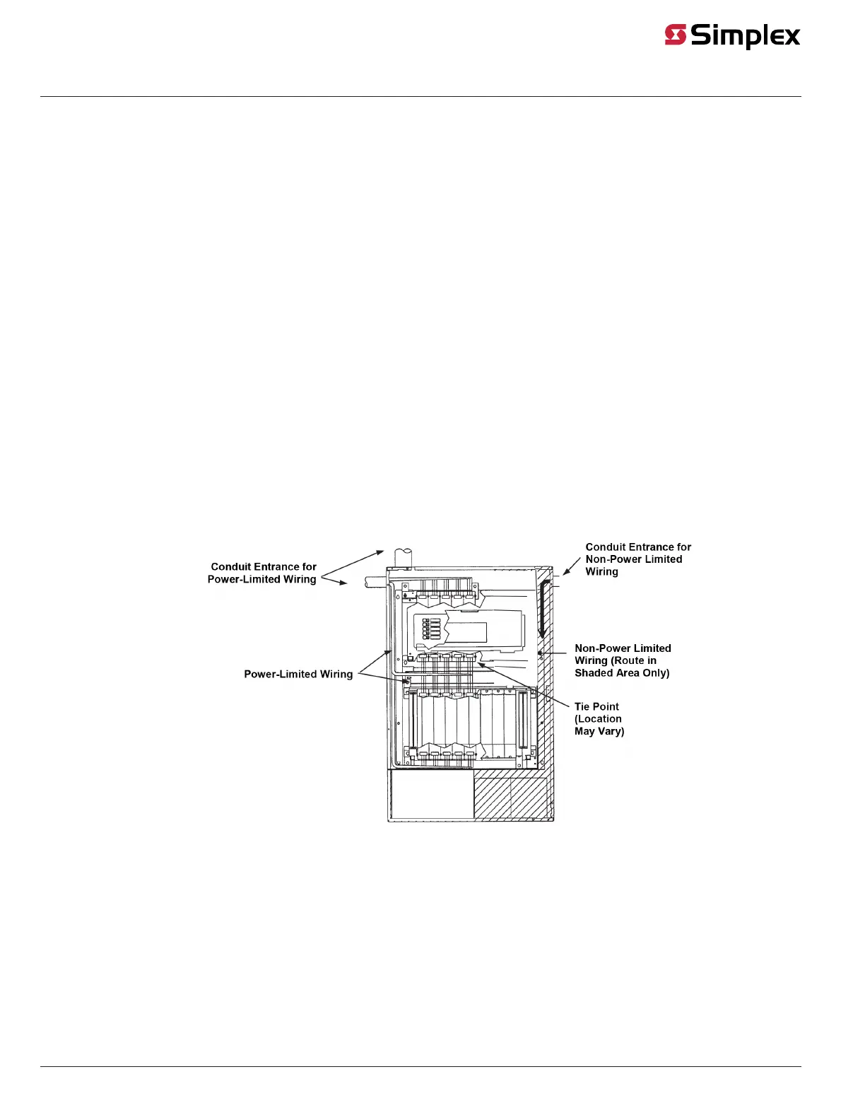
• Non-power limited field wiring (AC power, batteries, City connection) must be installed and routed in the shaded areas shown in Figure 9.
• Power-limited field wiring must be installed and routed in the non-shaded shown in Figure 9, with the exception of City wiring. Excess slack
should be kept to a minimum inside the back box enclosure. The wiring should be neatly dressed and bundled together using wire ties. Anchor
power-limited wiring to tie points.
• Tie the wiring located between bays to the internal wiring troughs, if applicable.
• When powering remote units or switching power through relay contacts, power for these circuits must be provided by a power-limited power
supply listed for fire-protective signaling use.
Figure 9: Power-Limited Wiring Guidelines
Class B IDNAC Wiring
The EPS has three SLCs for power and communication wiring.
Each SLC powers and communicates with up to 127 IDNAC devices. The EPS is wired to compatible devices and appliances, such as the TrueAlert ES
and TrueAlert Addressable lines (both multi and fixed candela), using Class B circuitry.
Class B wiring allows “T” tapping. EPS wiring is inherently supervised due to individual device level communications. End-of-line resistors are not
required.