page 6 579-1015 Rev U
4100ES Extended Power Supply Installation Instructions
Connection to the Power Distribution Module
The EPS is powered by the Power Distribution Module (PDM). The PDM takes power directly from a dedicated AC line and the two backup batteries,
and distributes power to each bay in the cabinet.
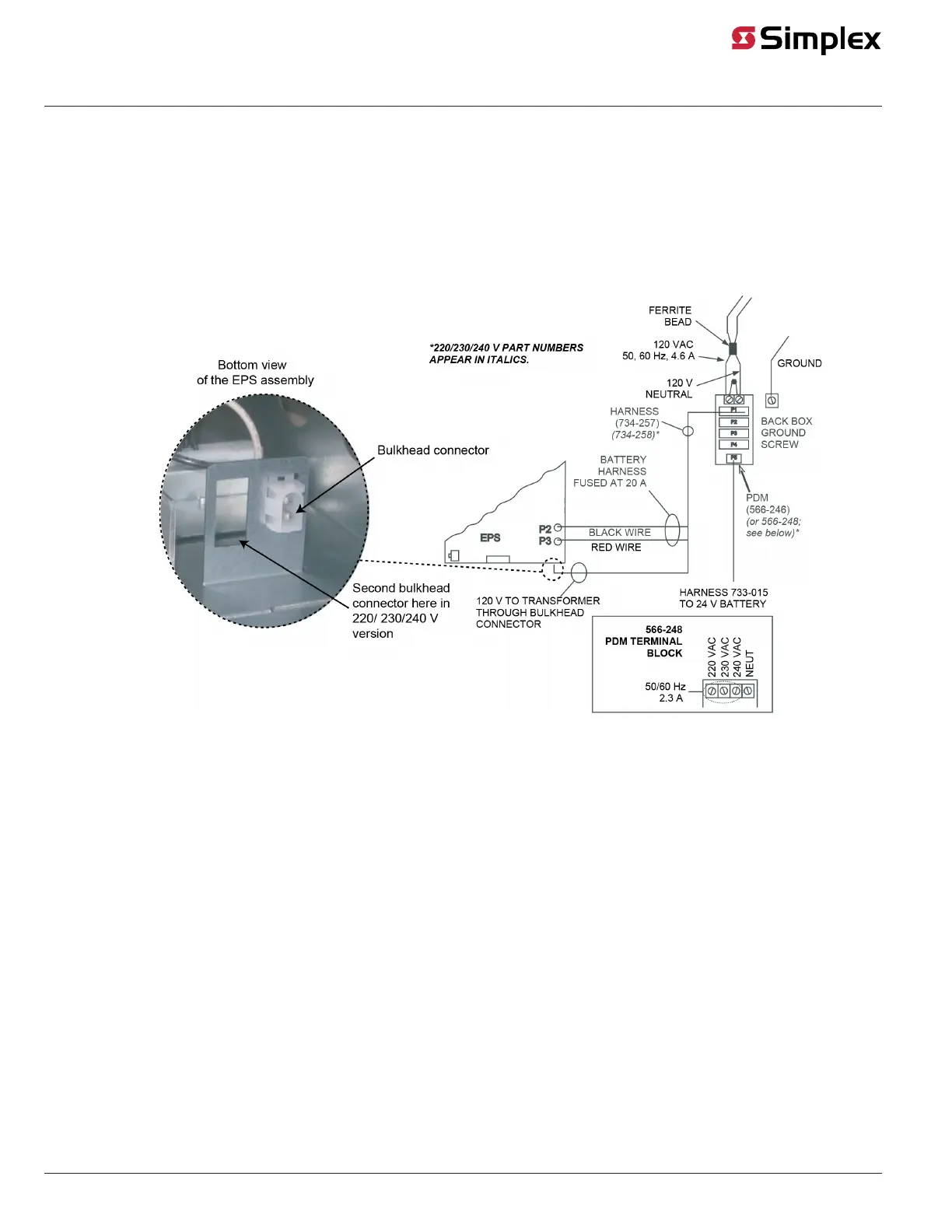
To connect the EPS to the PDM using Harness 734-257:
1. Ensure that the PDM is connected to an incoming 120 VAC power source. Keep the AC wires to the right side of the cabinet, in the non-
power-limited area, and at least one inch away from all other wires.
2. Connect the harness connector to the PDM.
3. Connect the separate Red and Black wires (with yellow female terminations) to Plugs P2 (black) and P3 (red) on the EPS.
4. Connect the white and black wires, which terminate together in a white snap-on connector, to the bulkhead connector at the bottom of the
EPS assembly.
Figure 8: PDM/Battery Connections
Connection to the IDNet channel
The EPS connection to the IDNet channel is made through the optional IDNet card installed on the EPS.
• For EPS modules fitted with an IDNet2 card, refer to manual 579-1169 for wiring and programming information.
• For EPS modules fitted with an IDNet1+ card (EPS+), refer to manual 579-1014 for wiring and programming information.