page 3 579-1015 Rev U
4100ES Extended Power Supply Installation Instructions
Installation
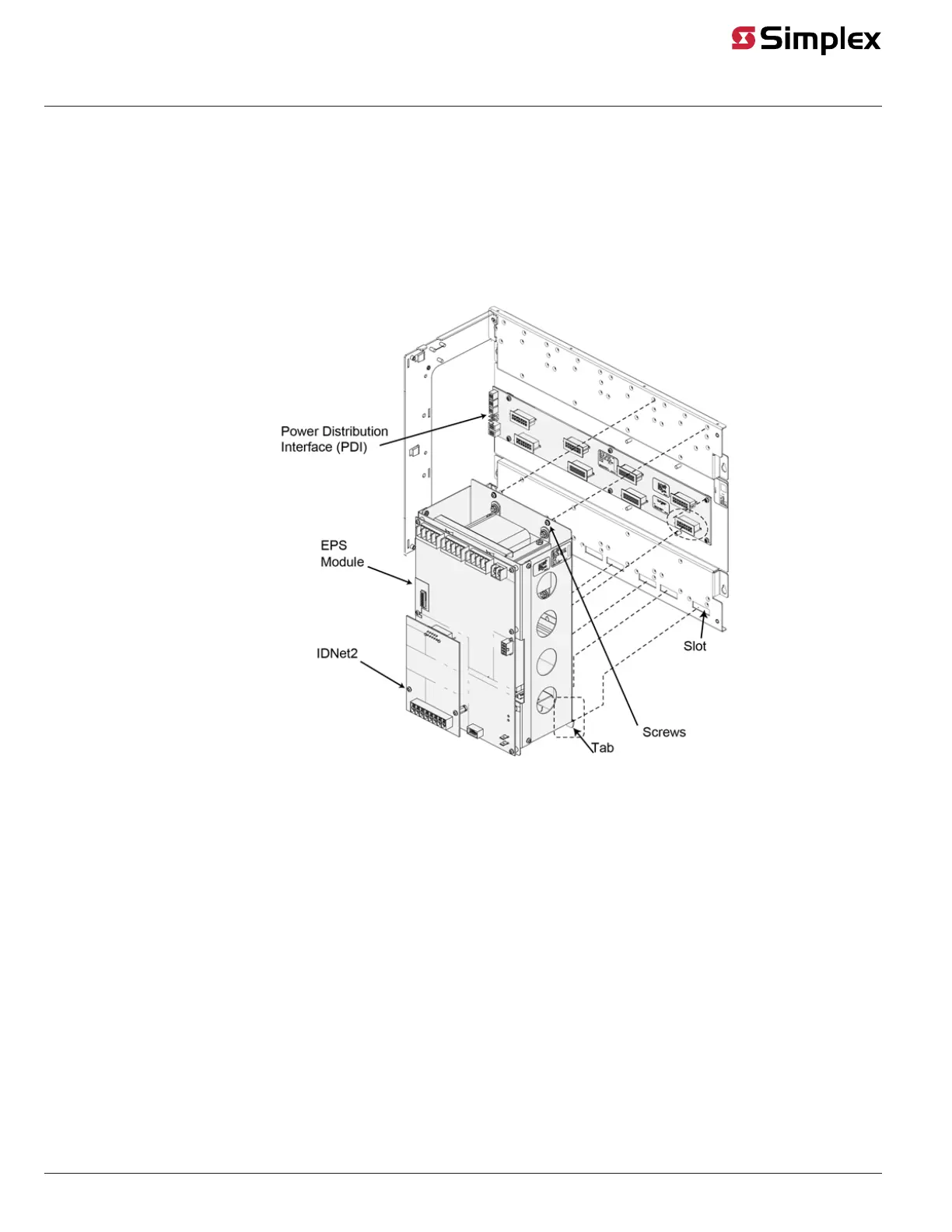
The EPS module mounts onto the Power Distribution Interface (PDI) in the last connector on the right side of the PDI.
• EPS modules mount into expansion bays.
• EPS + modules can either be mounted into an expansion bay or into a CPU bay. See revision AG or later of the 4100ES Installation Guide
574-848 for more information on mounting the EPS into a CPU bay.
Mounting
1. Insert the tabs at the bottom of the EPS module into the four slots on the bottom extreme right side of the mounting bay.
2. Gently tilt the module up straight against the mounting bay while ensuring proper connection between the EPS connector and the PDI
connector.
3. While securing the module with one hand, use the provided hardware to attach the top portion of the module to the mounting bay.
Figure 3: Mounting the EPS (EPS with IDNet2 card depicted)