page 4 579-1015 Rev U
4100ES Extended Power Supply Installation Instructions
Configurations
Setting the Address
The DIP Switch SW2 is used to set the EPS address as identified in the Panel Programmer job (see the section on Programming for more information).
From left to right, these switches are designated as SW2-1 through SW2-8. The function of these switches is as follows:
• SW2-1. This switch sets the baud rate for the internal 4100 communications line running between the card and the 4100 CPU. Set this switch
to ON.
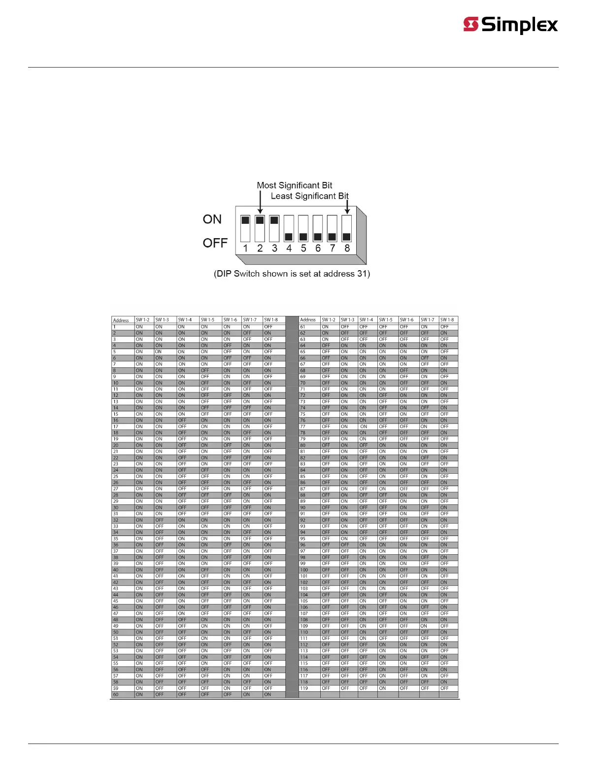
• SW2-2 through SW1-8. These switches set the card’s address within the FACU. Refer to Figure 5 for a complete list of the switch settings for all
of the possible card addresses.
You must set these switches to the value assigned to the module by the Panel Programmer.
Figure 4: DIP Switch SW2
Figure 5: EPS Card Addresses