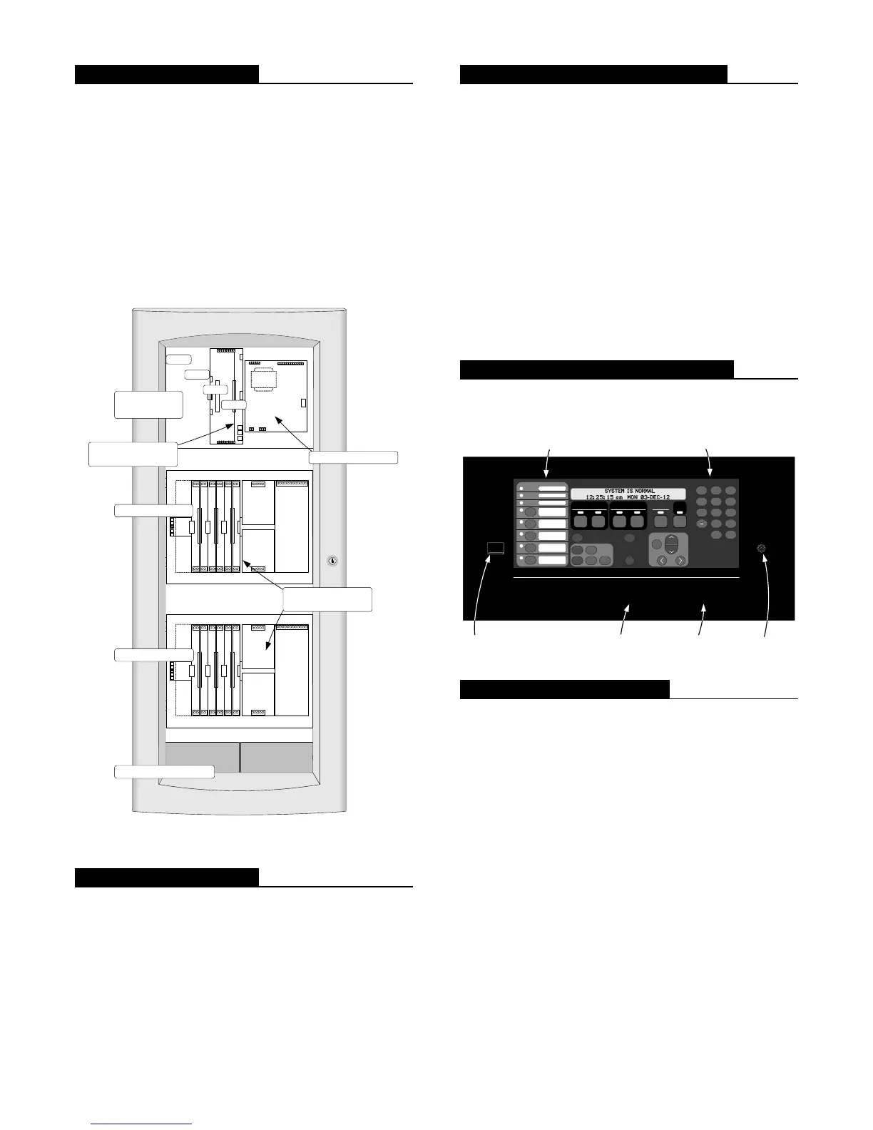
Module Bay Description
The Master Controller Bay (top) includes a standard
multi-featured system power supply, the master controller
board, and operator interface equipment.
The Expansion Bays include a Power Distribution
Interface (PDI) for new 4” x 5” flat design option
modules and also accommodate 4100-style modules.
The Battery Compartment (bottom) accepts two
batteries, up to 50 Ah, to be mounted within the cabinet
without interfering with module space.
The following illustration identifies bay locations using a
three bay cabinet for reference.
PDI
4x5 Module
Expansion Power
Supply
(XPS)
4x5 Module
I/O Wiring
I/O Wiring
I/O Wiring
4100 Option
4100 Option
4100 Option
Slot 1 Slot 2 Slot 3 Slot 4 Slot 5Slot 6Slot 7Slot 8
(Block E)
(Block F)
(Blocks G & H)
System Power
Supply
(SPS)
IDNet
NACs 1, 2 & 3
Aux Pwr
Aux
Relay
Btry
+
-
Master Controller
Board
Slot 1 Slot 2 Slot 3 Slot 4 Slot 5 Slot 6 Slot 7 Slot 8
Slot 1
Slot 2
Slot 4
Slot 3
PDI
4x5 Module
Expansion Power
Supply
(XPS)
4x5 Module
I/O Wiring
I/O Wiring
I/O Wiring
4100 Option
4100 Option
4100 Option
Slot 1 Slot 2 Slot 3 Slot 4 Slot 5Slot 6Slot 7Slot 8
(Block E)
(Block F)
(Blocks G & H)
Master
Controller Bay
Expansion Bay 1
Battery Compartment
System power supply
Master controller with
dual slot motherboard
Expansion Bay 2
Typical bays with
mixed module sizes
4100ES Module Bay Reference
Mechanical Description
Boxes can be close-nippled; each box provides
convenient stud markers for drywall thickness and
nail-hole knockouts for quicker mounting
Smooth box surfaces are provided for locally cutting
conduit entrance holes exactly where required
Cabinet assembly design has been seismic tested and is
certified to IBC and CBC standards as well as to
ASCE 7-05 category D, requires 33 Ah or 50 Ah
batteries with battery brackets as detailed on data sheet
S2081-0019
Mechanical Description (Continued)
The latching dress panel (retainer) assembly easily
lifts off for internal access
NACs are mounted directly on power supply
assemblies providing minimized wiring loss, compact
size, and readily accessible terminations
Packaging supports traditional 4100-style
motherboard with daughter cards
Modules are power-limited (except as noted, such as
relay modules)
The NEMA 1 box is ordered separately and available
for early installation
Doors are available with tempered glass inserts or
solid; boxes and doors are available in platinum or red
Boxes and door/retainer assemblies are ordered
separately per system requirements; refer to data sheet
S4100-0037 for details
Operator Interface Detail Reference
The following illustration identifies the primary functions
of the operator interface.
Press ACK located under flashing indicator.
Repeat operation u ntil all events are acknow ledged.
Local tone will silence.
A B C
AC Power
D E F G H I
J K L M N O P Q R
'SP' ( ) , 0 :
S T U V W X Y Z /
ALARMS
Fire Alarm Priority 2 Alarm
SYSTEM WARNINGS
Supervisory Trouble
Alarm Silenced
Emergency Operating Instructions
Alarm or Warning Condition
How to Acknowledge / View Events
How to Silence Building Signals
System indicat or flashing. Tone On. Press Alarm Sile nce.
How to Reset System
Press System Reset.
Press Ack to silence tone de vice.
ZONE
1
SIG
2
AUX
3
FB
4
IO
5
IDNet
6
P
7
A
8
L
9
NET ADDR
0
DEL
Enter C/Exit
Fire Alarm
Ack
Priority 2
Ack
Supv
Ack
Trouble
Ack
Alarm
Silence
System
Reset
Event
Time
Enable
On
Arm
Disable
Off
Disarm
Auto
Lamp
Test
More
Info
Menu
Previous
Next
Upload/Download
Ethernet port access
(under sliding cover)
Basic operator instructions
are printed on the interface
mounting plate
Panel sounder
Operator interface panel is directly
viewable and accessible (no access door)
Software Feature Summary
TrueAlarm individual analog sensing with front panel
information and selection access
“Dirty” TrueAlarm sensor maintenance alerts, service
and status reports including “almost dirty”
TrueAlarm magnet test indication appears as distinct
“test abnormal” message on display when in test mode
TrueAlarm sensor peak value performance report
“Install Mode” allows grouping of multiple troubles for
uninstalled modules and devices into a single trouble
condition (typical with future phased expansion); with
future equipment and devices grouped into a single
trouble, operators can more clearly identify events from
the commissioned and occupied areas
Module level ground fault searching assists installation
and service by locating and isolating modules with
grounded wiring
“Recurring Trouble Filtering” allows the panel to
recognize, process, and log recurring intermittent
troubles (such as external wiring ground faults), but
only sends a single outbound system trouble to avoid
nuisance communications
WALKTEST silent or audible system test performs an
automatic self-resetting test cycle
2 S4100-0031-21 12/2012