Input
Power
System Power Supplies (SPS)
Expansion Power Supplies (XPS)
Remote Power Supplies (RPS)
TrueAlert Power Supplies (TPS)
120 VAC Models 4 A maximum @ 102 to 132 VAC, 60 Hz
220-240 VAC
Models
2 A maximum @ 204 to 264 VAC, 50/60 Hz;
separate taps for 220/230/240 VAC
Power Supply Output
Ratings for SPS, XPS,
and RPS
(nominal 28 VDC on
AC; 24 VDC on battery
backup)
Total Power Supply
Output Rating
Including module currents and auxiliary power outputs;
9 A total for “Special Application” appliances; 4 A total for
“Regulated 24 DC” power (see below for details)
Output switches
to battery backup
during mains AC
failure or
brownout
conditions
Auxiliary Power Tap 2 A maximum
Rated 19.1 to 31.1 VDC
NACs Programmed
for Auxiliary Power
2 A maximum per NAC;
5 A maximum total
Special Application
Appliances
Simplex 4901, 4903, 4904, and 4906 Series horns, strobes, and combination horn/strobes and speaker/strobes
(contact your Simplex product representative for compatible appliances)
Regulated 24 DC
Appliances
Power for other UL listed appliances; use associated external synchronization modules where required
Battery Charger
Ratings for SPS,
RPS and TPS (sealed
lead-acid batteries)
Battery capacity range
UL listed for battery charging of 6.2 Ah up to 110 Ah (110 Ah batteries require a
remote battery cabinet); ULC listed for charging up to 50 Ah batteries
Charger characteristics
and performance
Temperature compensated, dual rate, recharges depleted batteries within 48
hours per UL Standard 864; to 70% capacity in 12 hours per ULC Standard S527
Environmental
Operating Temperature 32° to 120°F (0° to 49° C)
Operating Humidity Up to 93% RH, non-condensing @ 90° F (32° C) maximum
Additional Technical
Reference
Installation Instructions 574-848
Operating Instructions 579-197
8 S4100-0031-21 12/2012
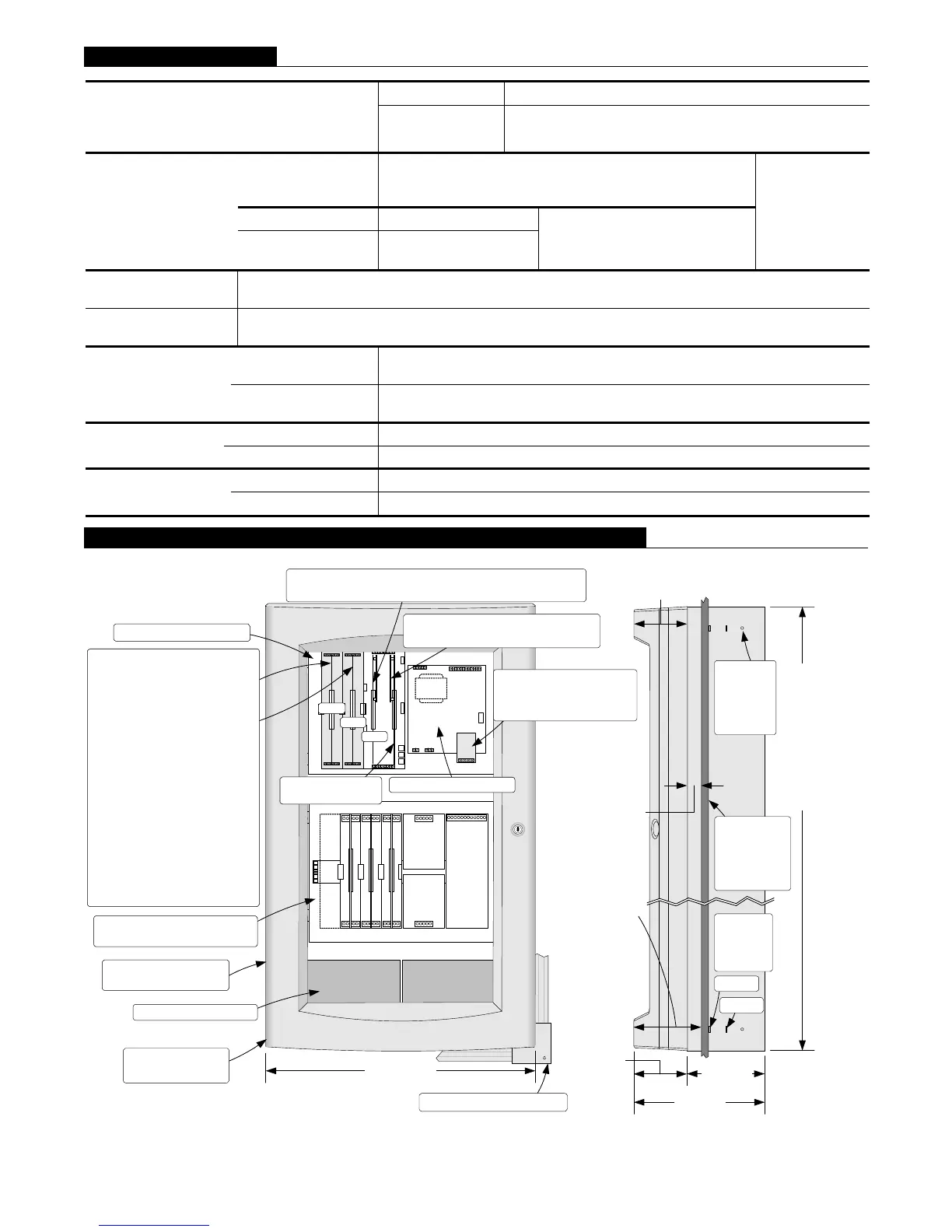
PDI
4x5 Module
Expansion Power
Supply
(XPS)
4x5 Module
I/O Wiring
I/O Wir ing
I/O Wiring
41 00 Op tion
41 00 Op tion
41 00 Op tion
Slot 1 Slot 2 Slot 3 Slot 4 Slot 5 Slot 6 Slot 7 Slot 8
(Block E)
(Bl ock F)
(Blocks G & H)
System Power
Supply
(SPS)
IDNet
NACs 1, 2 & 3
Aux Pwr
Aux
Relay
Btry
+
-
City Circuit
4100- 6031
4100- 6032
Alarm Relay
4100- 6033
Master Controller
Board
Slot 1 Slot 2 Slot 3 Slot 4 Slot 5 Slot 6 Slot 7 Slot 8
*System power supply
*Master controller
with motherboard
Optional semi-flush trim kit
4100-6031 or 4100-6032
City Circuit or 4100-6033
Alarm Relay
4100-6030 Service Modem mounts
only on master controller board
Slot 3, one 2" card: either 4100-6078 Network Module
with media cards or 4100-6038 Dual RS-232
Slot 1
Slot 2
Slot 3
Cabinet height:
(2 bay shown
for reference)
1 Bay = 22"
(559 mm)
2 Bay = 40"
(1016 mm)
3 Bay = 56"
(1427 mm)
Stud
alignment
markers,
each side
Knockout
screw/nail
holes (for
semi-flush
mounting)
4" stud
6" stud
Two, 2", or one, 4" slot for
one or two modules installed
per the following:
4100-6052 DACT, Slot 1
4100-6101 Physical Bridge,
Slot 2
4100-6102 Physical Bridge
(4" module) Slots 1 and 2
4100-6048 VESDA Interface,
Slot 1 or 2
4100-5005/5015 IDC Modules,
Slot 1 or 2
4100-6038 Dual RS-232,
Slot 2, if Network Module is
in Slot 3
Master Controller Bay
Typical Expansion Bay
(showing mixed module sizes)
Battery Compartment
Door can be hung
hinged left or right
Wall board
reference for
semi-flush
mounting,
6" stud
Two bay cabinet
shown without retainer
11-11/16"
(296 mm)
6-29/32"
(175 mm)
Door thickness
4-3/4"(121 mm)
Exposed cabinet for
semi-flush mounting
1-3/8" (35 mm)
minimum
Exposed door and
cabinet for semi-
flush mounting
6-1/8" (156 mm)
minimum
24" (610 mm)
Door 4-3/4"
(121 mm)
General Specifications
Mounting and CPU Bay Module Reference (* indicates supplied modules)
NOTE: A system ground must be provided for Earth Detection and transient protection devices. This connection
shall be made to an approved, dedicated Earth connection per NFPA 70, Article 250, and NFPA 780.