19
2.5 V.
10 V.
1V.
25 V.
50 A.
AMPS.
250 V.
500 V.
I000 V.
+
COMMON
-
A .C . V O LTS
ONLY
A.C.
A.C.
2.5 V.A.C.
260
ALL TERMINALS 1 V MAX
FIGURE 4-4. Frequency Response,
AC Voltage Ranges
PERCENT RELATIVE ERROR
+5
+4
+3
+2
+1
0
-1
-2
-3
-4
-5
10Hz
100Hz 1KHz 10KHz
100KHz
FREQUENCY
2.5 VAC RANGE
10 VAC RANGE
25 VAC RANGE
50 VAC RANGE
250 VAC RANGE
500 VAC RANGE
1000 VAC RANGE
AC VOLTAGE RANGES
1MHz
Before proceeding with the following steps, review the Safety Precautions in
Paragraph 4.1.
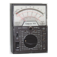
a. Set the function switch to AC
Volts Only position (Figure 4-
5).
NOTE: The meter will not indicate if
the switch is incorrectly set to a DC
position.
b. Set the range switch at one of
the five voltage range positions
marked 2.5V, 10V, 25V, 50V or
250V. (When in doubt as to ac-
tual voltage present, always
use the highest voltage range
as a protection to the Instru-
ment. If the voltage is within a
lower range, the switch may be
set for the lower range to ob-
tain a more accurate reading.)
c. Plug the black test lead into the
– COMMON jack and the red
test lead into the + jack.
d. Turn off power to the circuit to
be measured and discharge
any capacitors.
e. Connect the test leads across
the circuit voltage to be mea-
sured with the black lead to the
grounded side.
f. For the 2.5V range read the
value directly on the scale
marked 2.5 VAC. For the 10V,
25V, 50V and 250V ranges, read
the red scale marked AC and
use the black figure immedi-
ately above the scale.
4.11 AC Voltage Measurement 0-500V Range
Use extreme care when working in high voltage circuits. Do not handle the
Instrument or test leads while the circuit being measured is energized. OB-
SERVE ALL SAFETY PRECAUTIONS in paragraph 4.1 and in the instruction
manual for the equipment being tested.
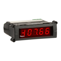
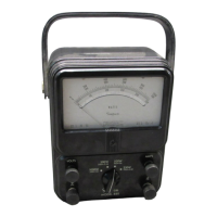
Figure 4-5. Jacks and Switch Positions
for Measuring AC Voltage 0-2.5 through
0-250V Ranges

 Loading...