| 23
Operation | HS80/MX575C/MX575D User Manual
GPS receiver uses a complex algorithm incorporating satellite locations and ranges to each
satellite to calculate the geographic location and heading. Reception of any four or more GPS
signals allows the receiver to compute three-dimensional coordinates and a valid heading.
Dierential operation
The purpose of differential GPS (DGPS) is to remove the effects of selective availability (SA),
atmospheric errors, timing errors, and satellite orbit errors, while enhancing system integrity.
Autonomous positioning capabilities of the Smart GPS compass will result in positioning
accuracies of 4.0 m 95% of the time. In order to improve positioning quality to better than 1.0
m 95%, the Smart GPS compass is able to use differential corrections received through the
internal beacon receiver (for MX575C/MX575D), SBAS demodulator or through externally-
supplied RTCM corrections.
SBAS tracking
The HS80/HS80A can scan and track SBAS signals without the need to tune the receiver. The
HS80/HS80A features two-channel tracking that provides an enhanced ability to maintain
a lock on an SBAS satellite when more than one satellite is in view. This redundant tracking
approach results in more consistent tracking of an SBAS signal in areas where signal blockage
of a satellite is possible. The MX575C/MX575D is configured to receive beacon DGPS
corrections. However, it can also be configured to receive SBAS or external RTCM corrections
from the SIMRAD-MX CDU.
Beacon operation
Many marine authorities, such as the U.S. coast guard, have installed networks of radio beacon
stations that broadcast DGPS corrections to users of this system. With the increasing utility of
these networks for terrestrial applications, there is an increasing trend toward densification
of these networks inland. The dual channel beacon receiver in the MX575C/MX575D can
operate in manual or automatic tuning mode, or, using database mode, will select the closest
station in compliance with IEC 61108-4 standards. The MX575C/MX575D is configured to
receive DGPS corrections from beacon stations by default.
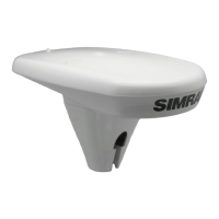
Smart GPS compass overview
The Smart GPS compass provides accurate and reliable heading and position information at
high update rates. To accomplish this task, the Smart GPS compass uses a high performance
GPS receiver and two antennas for GPS signal processing. One antenna is designated as the
primary GPS antenna and the other is the secondary GPS antenna. Positions computed by
the Smart GPS compass are referenced to the phase center of the primary GPS antenna.
Heading data references the vector formed from the primary GPS antenna phase center to
the secondary GPS antenna phase center.
The heading arrow located on the bottom of the Smart GPS compass enclosure defines
system orientation. The arrow points in the direction the heading measurement is computed
(when the antenna is installed parallel to the fore-aft line of the vessel). The secondary
antenna is directly above the arrow.
Fixed baseline moving base station RTK
The Smart GPS compass’s internal GPS receiver uses both the L1 GPS C/A code and carrier
phase data to compute the location of the secondary GPS antenna in relation to the primary
GPS antenna with a very high sub-centimeter level of precision. The technique of computing
the location of the secondary GPS antenna with respect to the primary antenna, when the
primary antenna is moving, is often referred to as moving base station Real Time Kinematic
(or moving base station RTK).
Generally, RTK technology is very sophisticated and requires a significant number of possible
solutions to be analyzed where various combinations of integer numbers of L1 wavelengths
to each satellite intersect within a certain search volume. The integer number of wavelengths
is often referred to as the “ambiguity” as they are initially ambiguous at the start of the RTK
solution.
The Smart GPS compass restricts the RTK solution. It does this knowing that the secondary
GPS antenna is 50 cm from the primary GPS antenna. This is called a fixed baseline and it
defines the search volume of the secondary antenna as the surface of a sphere with radius 50