6 |
Installation | HS80/HS80A/MX575C/MX575D UserManual
Installation
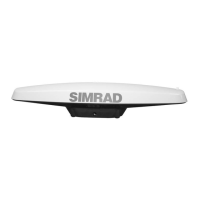
Mounting location
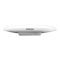
This section provides information on determining the best location for the Smart GPS compass.
GPS reception
When considering where to mount the Smart GPS compass, consider the following GPS
reception recommendations:
• Consider GPS reception, ensuring there is a clear view of the sky available to the Smart
GPS compass so the GPS satellites are not masked by obstructions that may reduce system
performance
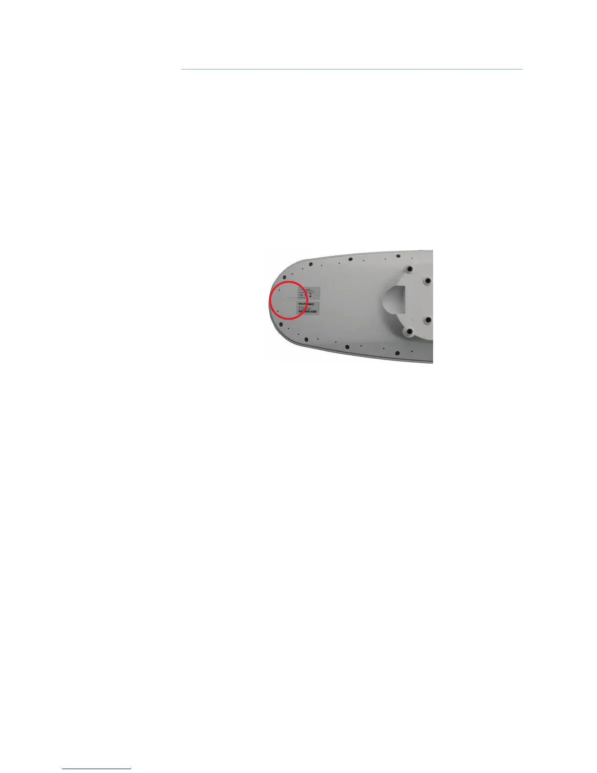
• Since the Smart GPS compass computes a position based on the internal primary GPS antenna
element, mount the Smart GPS compass where you desire a position with respect to the
primary GPS antenna (located on the end opposite the recessed arrow on the underside of the
enclosure).
• Locate any transmitting antennas away from the GPS Compass by at least a few meters to
ensure tracking performance is not compromised, giving you the best performance possible
• Make sure there is enough cable length to route into the vessel to reach a breakout box or
terminal strip
• Do not locate the antenna where environmental conditions exceed those specified in
“Environmental” on page 32.
Beacon reception
When using the MX575C/MX575D internal beacon receiver as the correction source, consider
the possible mounting locations from the perspective of ambient noise within the beacon
band (300 KHz).
Keep the following in mind when deciding upon a location with respect to maximizing beacon
performance:
• Ensure that the antenna is as far as possible from all other equipment that emits electromagnetic
interference (EMI) such as DC motors, alternators, solenoids, radio transmitters, power cables,
display units, and other electronic devices.
• If you are installing the antenna on a vessel, mount the MX575C/MX575D considering
maintenance and accessibility. In addition, ensure that the antenna is not obscured by the
metal mast, guy wires or metal railings on the vessel.
• If radar(s) or INMARSAT system is present, mount the GPS Compass antenna outside the path
of the transmission beam.
The MX575C/MX575D’s internal beacon receiver calculates a signal-to-noise ratio (SNR),
measured in decibels (dB) that indicates the receiver’s performance. The SNR is the height of the
signal above the noise floor: the higher the SNR, the better your beacon receiver demodulates
the signal. The optimum antenna location will be a position where your average SNR is highest.
You should turn on all accessories that you intend to use during normal operation when
locating the best position for the antenna. By monitoring the SNR, you can determine the
optimum location with respect to beacon reception. The SNR is available in the GPS6 (Beacon
Status) screen of the MX CDU.
2