M
ultiFlame DF-TV7 Page 22 / 56 NOSP16358-03 [04/2016]
Figure 4 : Terminal blocks
Point JP12 & JP13 Description
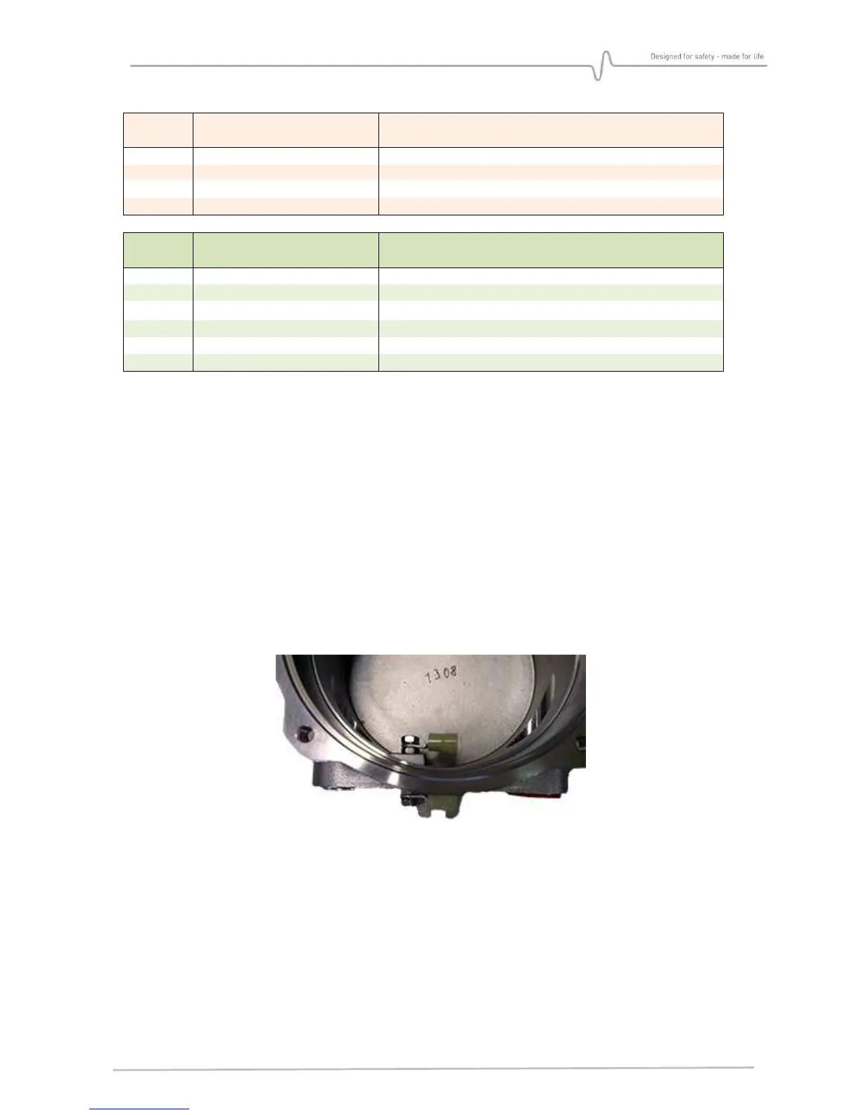
4.3.2. Connection of the electrical ground braid
Use a shield connection clamp (not supplied) to connect the shielding of the cable to the
electric ground of the housing (see below).
4.3.3. Grounding
A M4 screw passes through the body of the enclosure, enabling the electronic ground of the
housing to be connected to the local ground.
It is recommended to use a yellow / green wire with a ring lug (minimum diameter 1.5 mm).
The armour of the power cable is normally connected to the ground of the detector, but it
may depend on site practices.